AC simulation in Xschem


Ming Sun / November 18, 2022
8 min read • ––– views
Test bench
The test bench of the closed loop simulation for a single stage OTA is as shown in Fig. 1.


The properties of the key components used in the test bench are listed below.
Netlist & sim: importlauncher.symfromxschem_library/deviceslibrary and change its property as follows:
name=h3
descr="Netlist & sim"
tclcommand="xschem netlist; xschem simulate"
Load/unload Tran waveforms: importlauncher.symfromxschem_library/deviceslibrary and change its property as follows:
name=h4
descr="Load/unload
Tran waveforms"
tclcommand="
xschem raw_read $netlist_dir/[file tail [file rootname [xschem get current_name]]].raw tran
"
Load/unload AC waveforms: importlauncher.symfromxschem_library/deviceslibrary and change its property as follows:
name=h4
descr="Load/unload
Tran waveforms"
tclcommand="
xschem raw_read $netlist_dir/[file tail [file rootname [xschem get current_name]]].raw ac
"
stimulus: importcode.symfromxschem_library/deviceslibrary and change its property as follows:
name=NGSPICE
only_toplevel=true
value="
.option savecurrents
.control
  save all
  save @m.xm1.msky130_fd_pr__nfet_01v8[gm]
  save @m.xm1.msky130_fd_pr__nfet_01v8[id]
  save @m.xm1.msky130_fd_pr__nfet_01v8[vgs]
  save @m.xm1.msky130_fd_pr__nfet_01v8[vds]
  save @m.xm1.msky130_fd_pr__nfet_01v8[cgg]
  save @m.xm1.msky130_fd_pr__nfet_01v8[vdsat]
  save @m.xm1.msky130_fd_pr__nfet_01v8[vth]
  save @m.xm1.msky130_fd_pr__nfet_01v8[gds]
  save @m.xm2.msky130_fd_pr__nfet_01v8[gm]
  save @m.xm2.msky130_fd_pr__nfet_01v8[id]
  save @m.xm2.msky130_fd_pr__nfet_01v8[vgs]
  save @m.xm2.msky130_fd_pr__nfet_01v8[vds]
  save @m.xm2.msky130_fd_pr__nfet_01v8[cgg]
  save @m.xm2.msky130_fd_pr__nfet_01v8[vdsat]
  save @m.xm2.msky130_fd_pr__nfet_01v8[vth]
  save @m.xm2.msky130_fd_pr__nfet_01v8[gds]
  save @m.xm3.msky130_fd_pr__nfet_01v8[gm]
  save @m.xm3.msky130_fd_pr__nfet_01v8[id]
  save @m.xm3.msky130_fd_pr__nfet_01v8[vgs]
  save @m.xm3.msky130_fd_pr__nfet_01v8[vds]
  save @m.xm3.msky130_fd_pr__nfet_01v8[cgg]
  save @m.xm3.msky130_fd_pr__nfet_01v8[vdsat]
  save @m.xm3.msky130_fd_pr__nfet_01v8[vth]
  save @m.xm3.msky130_fd_pr__nfet_01v8[gds]
  save @m.xm4.msky130_fd_pr__nfet_01v8[gm]
  save @m.xm4.msky130_fd_pr__nfet_01v8[id]
  save @m.xm4.msky130_fd_pr__nfet_01v8[vgs]
  save @m.xm4.msky130_fd_pr__nfet_01v8[vds]
  save @m.xm4.msky130_fd_pr__nfet_01v8[cgg]
  save @m.xm4.msky130_fd_pr__nfet_01v8[vdsat]
  save @m.xm4.msky130_fd_pr__nfet_01v8[vth]
  save @m.xm4.msky130_fd_pr__nfet_01v8[gds]
  save @m.xm5.msky130_fd_pr__pfet_01v8[gm]
  save @m.xm5.msky130_fd_pr__pfet_01v8[id]
  save @m.xm5.msky130_fd_pr__pfet_01v8[vgs]
  save @m.xm5.msky130_fd_pr__pfet_01v8[vds]
  save @m.xm5.msky130_fd_pr__pfet_01v8[cgg]
  save @m.xm5.msky130_fd_pr__pfet_01v8[vdsat]
  save @m.xm5.msky130_fd_pr__pfet_01v8[vth]
  save @m.xm5.msky130_fd_pr__pfet_01v8[gds]
  save @m.xm6.msky130_fd_pr__pfet_01v8[gm]
  save @m.xm6.msky130_fd_pr__pfet_01v8[id]
  save @m.xm6.msky130_fd_pr__pfet_01v8[vgs]
  save @m.xm6.msky130_fd_pr__pfet_01v8[vds]
  save @m.xm6.msky130_fd_pr__pfet_01v8[cgg]
  save @m.xm6.msky130_fd_pr__pfet_01v8[vdsat]
  save @m.xm6.msky130_fd_pr__pfet_01v8[vth]
  save @m.xm6.msky130_fd_pr__pfet_01v8[gds]
  save @m.xm7.msky130_fd_pr__nfet_01v8[gm]
  save @m.xm7.msky130_fd_pr__nfet_01v8[id]
  save @m.xm7.msky130_fd_pr__nfet_01v8[vgs]
  save @m.xm7.msky130_fd_pr__nfet_01v8[vds]
  save @m.xm7.msky130_fd_pr__nfet_01v8[cgg]
  save @m.xm7.msky130_fd_pr__nfet_01v8[vdsat]
  save @m.xm7.msky130_fd_pr__nfet_01v8[vth]
  save @m.xm7.msky130_fd_pr__nfet_01v8[gds]
  op
  remzerovec
  write SIM_AC.raw
  set appendwrite
  ac dec 10 1 1e12
  remzerovec
  write SIM_AC.raw
  tran 10n 1m
  write SIM_AC.raw
.endc
"
- plot
Voutmagnitude in AC simulation: in waveform graph, add"Vout db20()" - plot
Voutphase in AC simulation: in waveform graph, addph(Vout)
Simulation results
The OTA is just a single stage OTA with a 10pF ideal capacitor as the load. From the analog IC design knowledge, we know that the cross over frequency of the closed loop transfer function can be written as:
From Fig. 1, we have back annotated the operating point to the schematic. So we can plug in the actual numbers and Eq. 2 becomes to:
From the simulation results, we can see that the cross over frequency from AC simulation results is ~187kHz. In the actual test bench, we add NMOS M7 to mimic the loading from the input pair M3.
Let us take Cgg into the consideration and Eq. 3 will become to:
From the AC simulation results, Fig. 2 shows the AC gain at 10kHz is around 25.35dB => 18.5

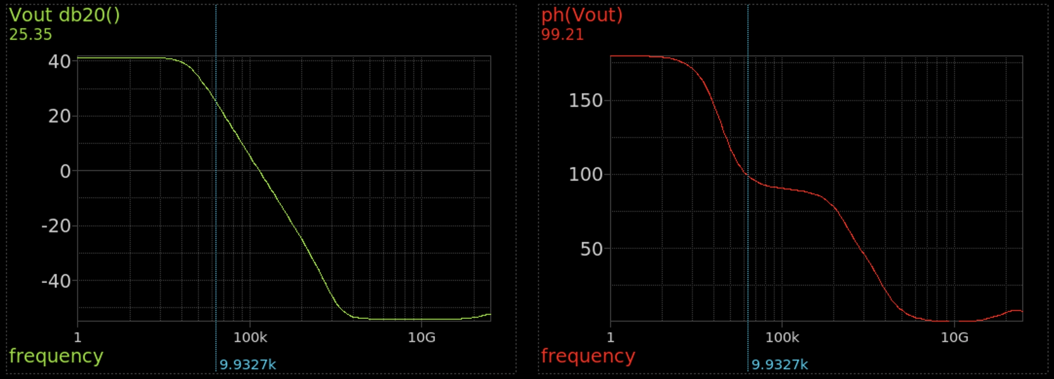
Fig. 3 shows the transient simulation results. For the 1mV sinewave input, the Vout ripple is about:
Eq. 3 matches with the prediction results as indicated by Fig. 2.
References and materials
[1] Closed loop stability simulation for a single stage OTA - schematic