ABCs of Voltage Mode in Switching Regulator Control


Ming Sun / October 19, 2021
6 min read • ––– views

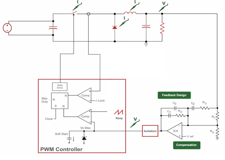
Voltage Mode Buck Block Diagram
Fig. 1 shows a Voltage-Mode Buck converter, where it contains asynchronous power stage, feedback resistor, Type-III compensator and PWM controller.
Concept
The output voltage Vout or the feedback voltage Vfb and Vref are feeding to the error amplifier (EA). The EA's output voltage is compared with an external ramp by the pwm comparator to generate the duty cycle information needed by the control loop.
It is difficult to compensate voltage mode controller due to the fact of the LC complex poles at the power stage output. Assuming L=1uH and C=4.7uF, the power stage output pole can be calculated as:
Considering the DC bias effect in the ceramic capacitor, its capacitance can vary as high as 90%. So the output pole can vary a lot in the actual design and application environment, which makes it difficult to design the voltage loop compensator.
If the LC complex poles fall within the crossover frequency, we have three poles which generates -270º phase fall off roughly speaking. Assuming 60º phase margin, the amount of phase boost we need can be calculated as:
150º phase boost would mean that we need a Type-III compensator to compensate the voltage mode controller.
Voltage mode control is a histroic mistake. We should avoid using voltage model control wherever we can.
-- Vadim Ivanov (TI fellow)
References
The references used in this article are listed below:
[2] Ray Ridley Youtube Video - Voltage Mode or Current Mode Control?
[3] Ray Ridley - Current or Voltage Model.pdf
[4] RIDLEYWORKS DEMO