Backannotation of operating point in Xschem


Ming Sun / November 06, 2022
10 min read • ––– views
In this tutorial, we will keep using the SIM_inv.sch schematic test bench. In the previous blog post[1], we use Ngspice to view the simulation results. Another alternative to view the simulation results is to use the built-in waveform viewer from Xschem.
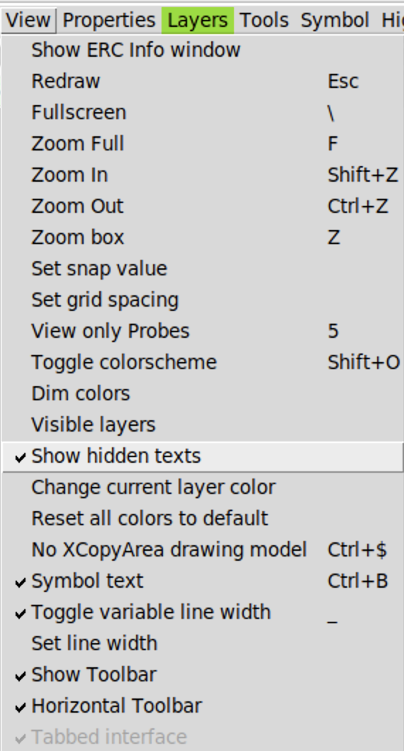
Show hidden text
Go to View => enable Show hidden text option. This will allow us to see gm and id from the MOSFET symbol.

Modify stimulus
In code_shown.sym block, modify the stimulus as follows:
name=NGSPICE
only_toplevel=true
value="
.control
save all
save @m.xm11.msky130_fd_pr__pfet_01v8[gm]
save @m.xm11.msky130_fd_pr__pfet_01v8[id]
save @m.xm11.msky130_fd_pr__pfet_01v8[vgs]
save @m.xm11.msky130_fd_pr__pfet_01v8[cgg]
save @m.xm11.msky130_fd_pr__pfet_01v8[vds]
save @m.xm11.msky130_fd_pr__pfet_01v8[vdsat]
save @m.xm1.msky130_fd_pr__nfet_01v8[gm]
save @m.xm1.msky130_fd_pr__nfet_01v8[id]
save @m.xm1.msky130_fd_pr__nfet_01v8[vgs]
save @m.xm1.msky130_fd_pr__nfet_01v8[vds]
save @m.xm1.msky130_fd_pr__nfet_01v8[cgg]
save @m.xm1.msky130_fd_pr__nfet_01v8[vdsat]
dc Vin 0 1.8 1m
op
write Sim_inv.raw
.endc
"
Basically, we will save gm, id, vgs, vdsat into the operating point.
Add additional probe
You can add addtional probe, such as ngspice_get_value.sym and ngspice_probe.sym from xschem_library/devices folder.
In my case, I placed two ngspice_get_value.sym probes in the schematic with the following contents:
name=r14 node=v(@m.xm11.msky130_fd_pr__pfet_01v8[vgs])
descr="vgs="
name=r1 node=v(@m.xm11.msky130_fd_pr__pfet_01v8[vds])
descr="vds="
Modify NMOS and PMOS symbol
I prefer to check the vgs, vds, cgg, vdsat directly from the symbol, similar to Spectre. What we can do is that we can modify the NMOS and PMOS symbol by adding more properties.
By default, after Skywater130 PDK installation, the NMOS and PMOS symbols are read only. To enable the write, we can use the following command:
sudo chmod a+rwx nfet_01v8.sym
sudo chmod a+rwx pfet_01v8.sym
Here I only enabled the write for 1.8V NMOS and PMOS. You can follow the same procedure to enable the write for other symbols as well.
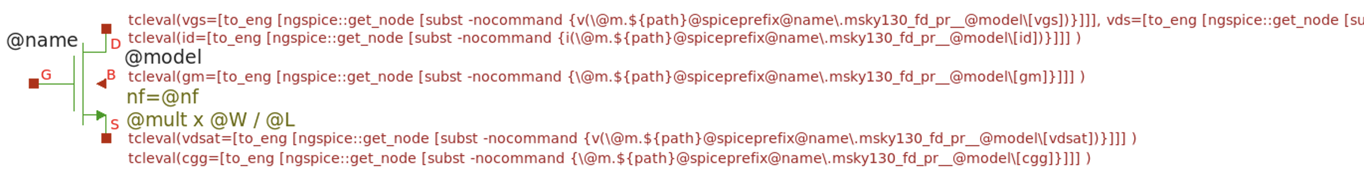
Then click NMOS symbol and press bindkey i to decend to its symbol. We can add the following properties:
tcleval(vgs=[to_eng [ngspice::get_node [subst -nocommand {v(\@m.${path}@spiceprefix@name\.msky130_fd_pr__@model\[vgs])}]]], vds=[to_eng [ngspice::get_node [subst -nocommand {v(\@m.${path}@spiceprefix@name\.msky130_fd_pr__@model\[vds])}]]])
tcleval(vdsat=[to_eng [ngspice::get_node [subst -nocommand {v(\@m.${path}@spiceprefix@name\.msky130_fd_pr__@model\[vdsat])}]]] )
tcleval(cgg=[to_eng [ngspice::get_node [subst -nocommand {\@m.${path}@spiceprefix@name\.msky130_fd_pr__@model\[cgg]}]]] )

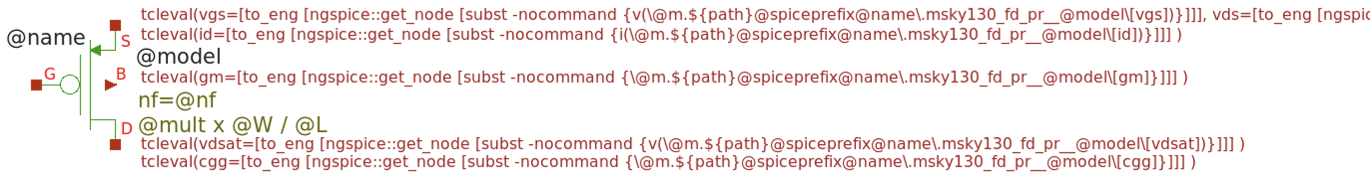
Similarly, we can follow the same above procedure to add more properties for 1.8V PMOS symbol as well.
Backannotation
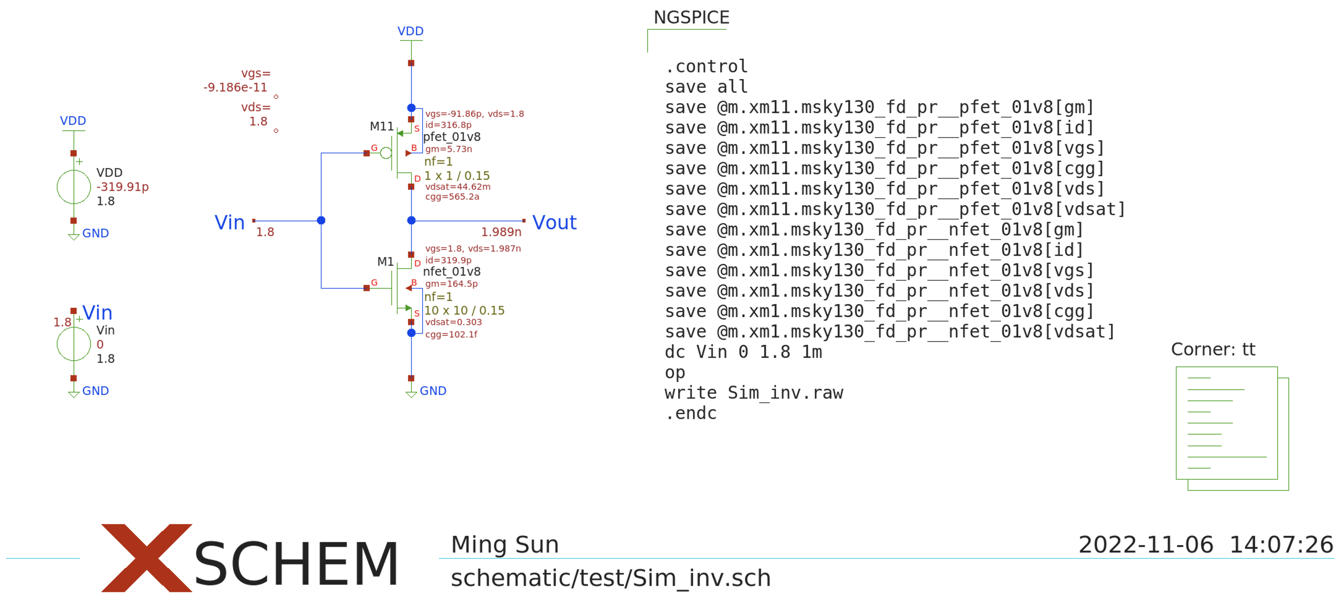
Click Netlist and then Simulate button. After the simulation is done, go to Simulation => Annotate Operating Point into schematic.

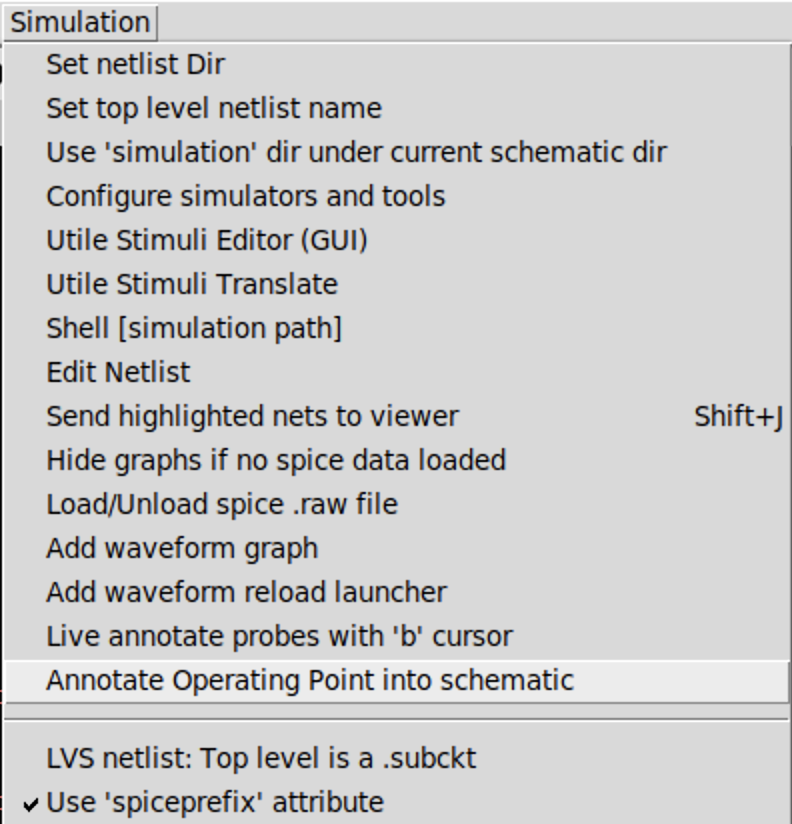
The backannotation results are shown in Fig. 5.

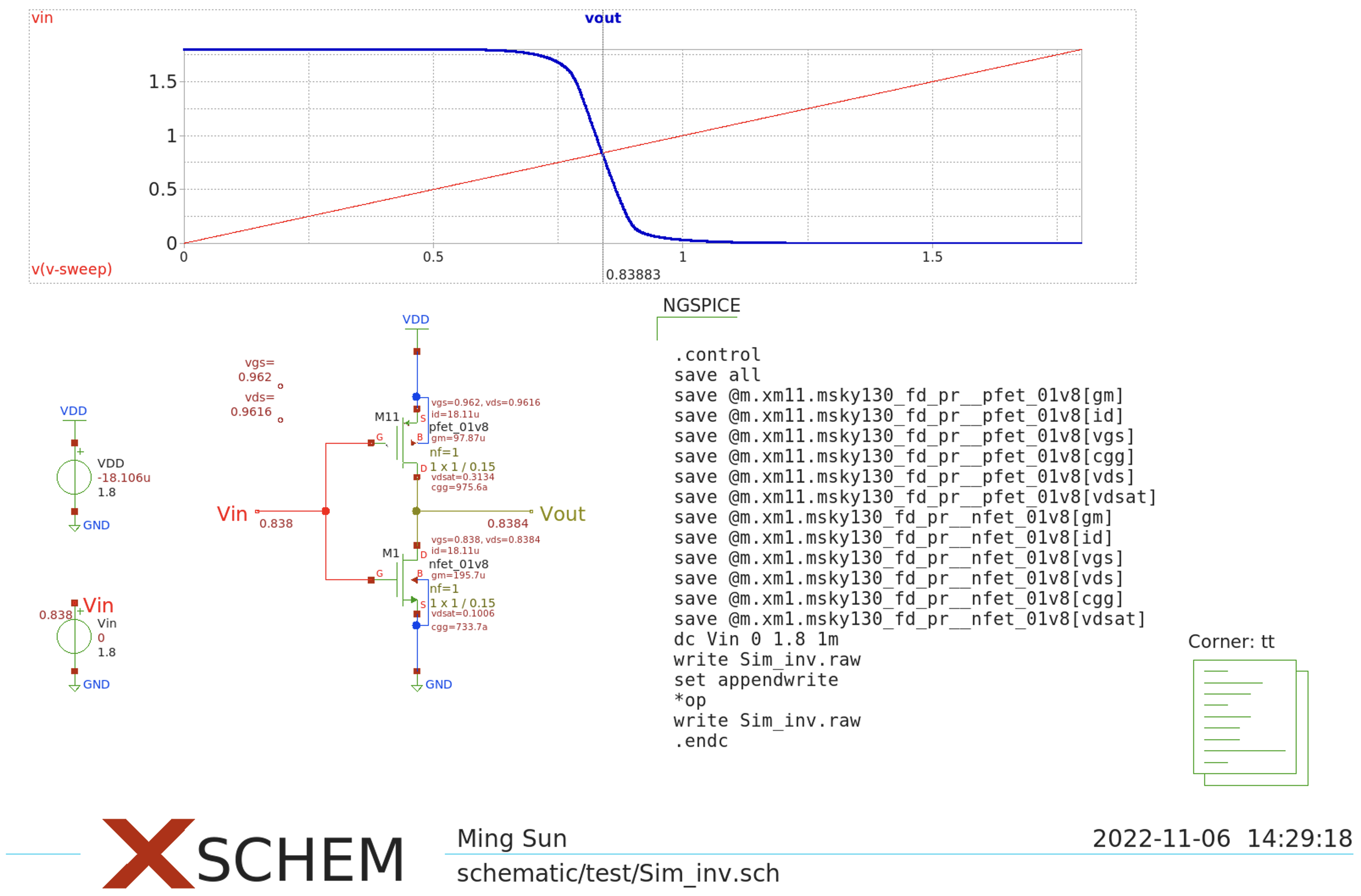
Live annotate
Another way to do the back annotation is to use the
Live annotateoption. To do so, add a waveform graph in the schematic.change the NMOS width
W=1and multipliermult=1as well.Then, modify the stimulus as follows:
name=NGSPICE
only_toplevel=true
value="
.control
save all
save @m.xm11.msky130_fd_pr__pfet_01v8[gm]
save @m.xm11.msky130_fd_pr__pfet_01v8[id]
save @m.xm11.msky130_fd_pr__pfet_01v8[vgs]
save @m.xm11.msky130_fd_pr__pfet_01v8[cgg]
save @m.xm11.msky130_fd_pr__pfet_01v8[vds]
save @m.xm11.msky130_fd_pr__pfet_01v8[vdsat]
save @m.xm1.msky130_fd_pr__nfet_01v8[gm]
save @m.xm1.msky130_fd_pr__nfet_01v8[id]
save @m.xm1.msky130_fd_pr__nfet_01v8[vgs]
save @m.xm1.msky130_fd_pr__nfet_01v8[vds]
save @m.xm1.msky130_fd_pr__nfet_01v8[cgg]
save @m.xm1.msky130_fd_pr__nfet_01v8[vdsat]
dc Vin 0 1.8 1m
write Sim_inv.raw
set appendwrite
*op
write Sim_inv.raw
.endc
"
At waveform graph, press bindkey
bto show thebcursorClick
Netlist=>SimulateClick waveform graph and then choose the net
Vin. Press bindkeyoption-gto sendVinwaveform into the waveform graph. Similarly, we can send theVoutdata to waveform graph as well.Go to
Simulation=>Load/unload spice .raw file. In the meanwhile, enable theLive annotate probes with 'b' cursoras well.When you move cursor
b, you can see that the annotation results change at the same time.

References and materials
[1] Backannotation of NGSPICE simulation operating point data into an XSCHEM schematic
[2] Xschem - 101