Basic RLC simulation in Xschem


Ming Sun / November 01, 2022
12 min read • ––– views
Step 1 - Create a new schematic
First go to your schematic folder and type the following command to create a schematic named rlc.sch.
xschem rls.sch

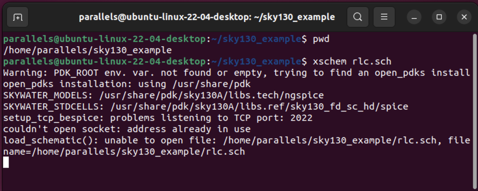
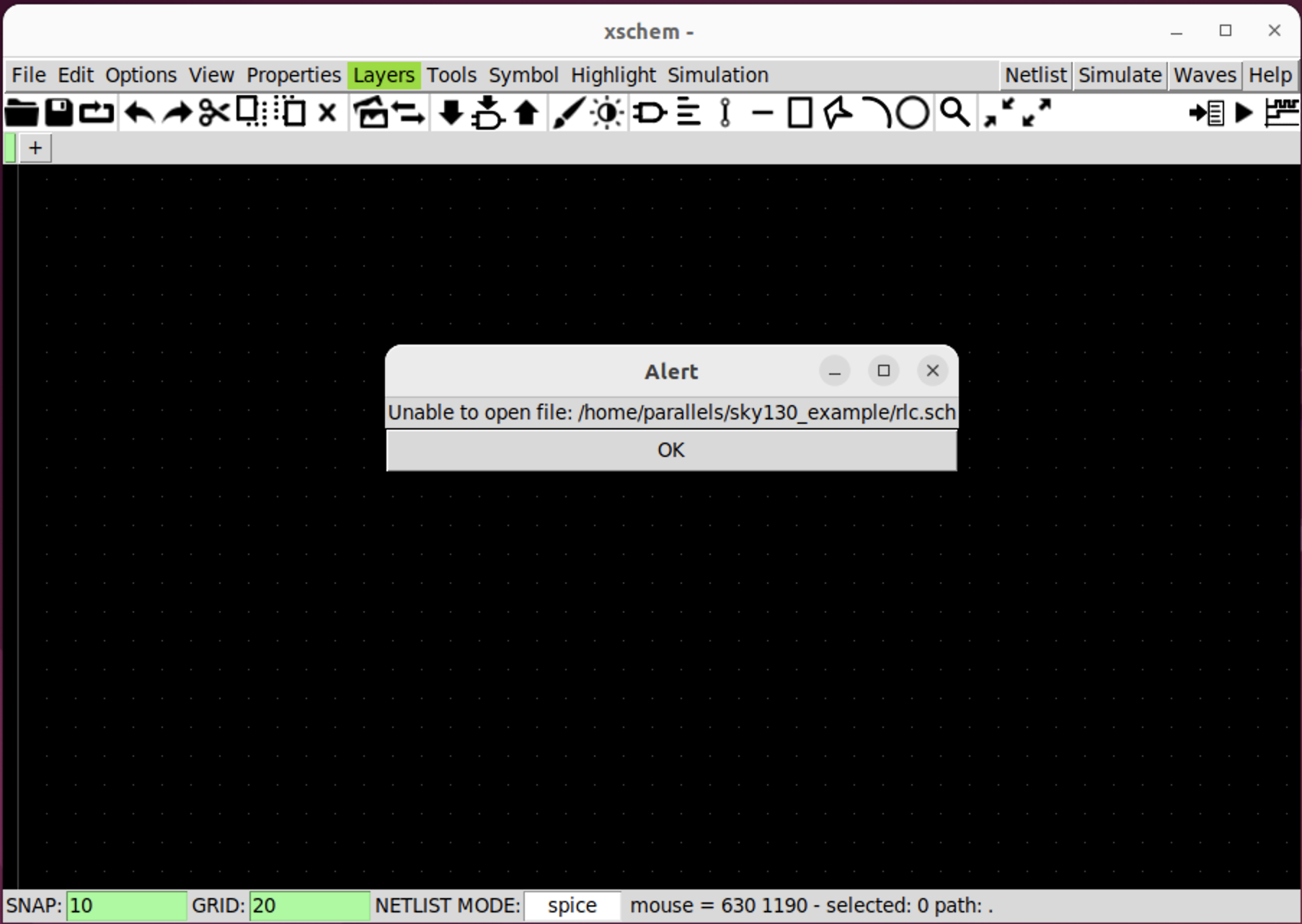
There will be an Alert pop up, which we can ignore.

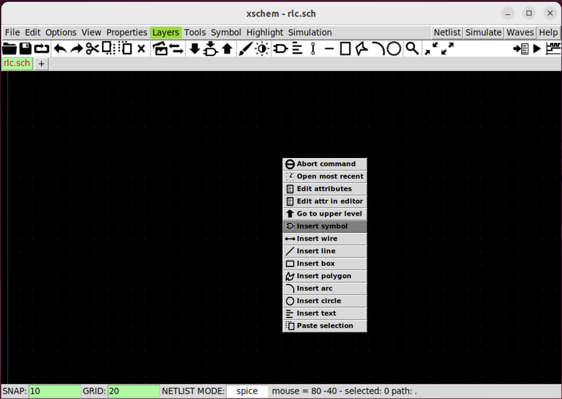
Step 2 - insert component symbol
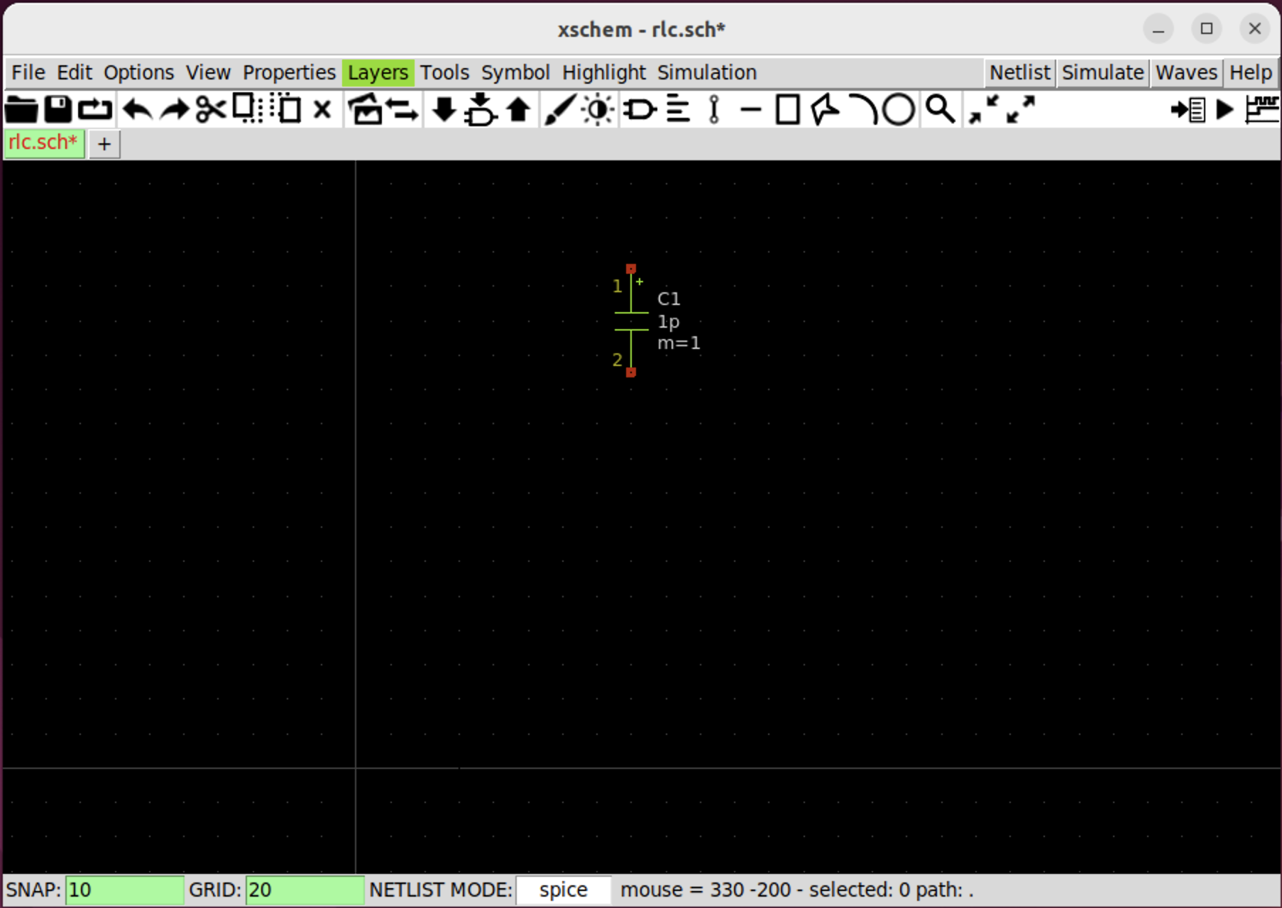
Right click on Xschem schematic, and choose insert symbol.
In the pop up window, choose xschem_library => devices. In the File/Search window, type cap.
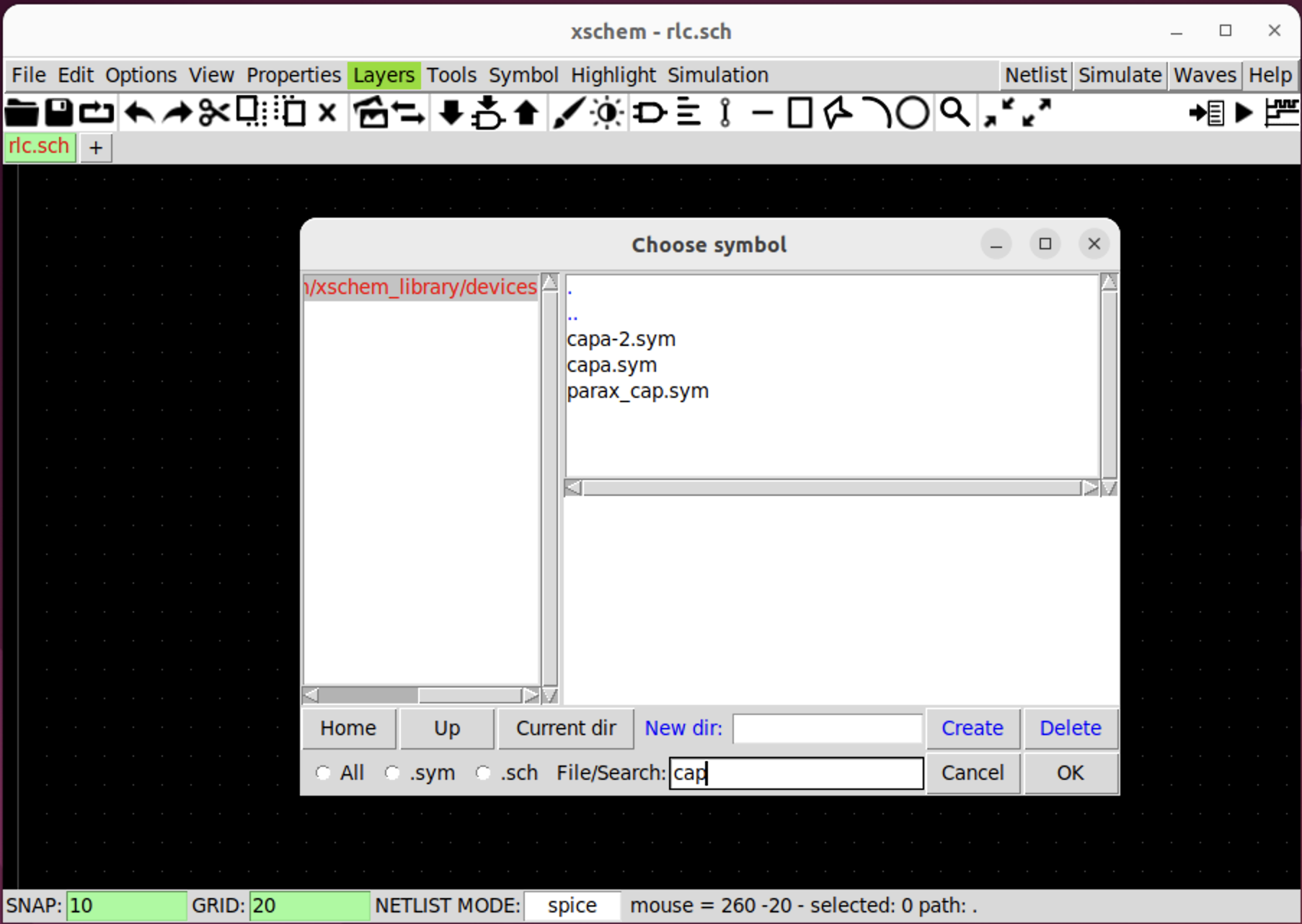
Choose capa.sym and click ok button.

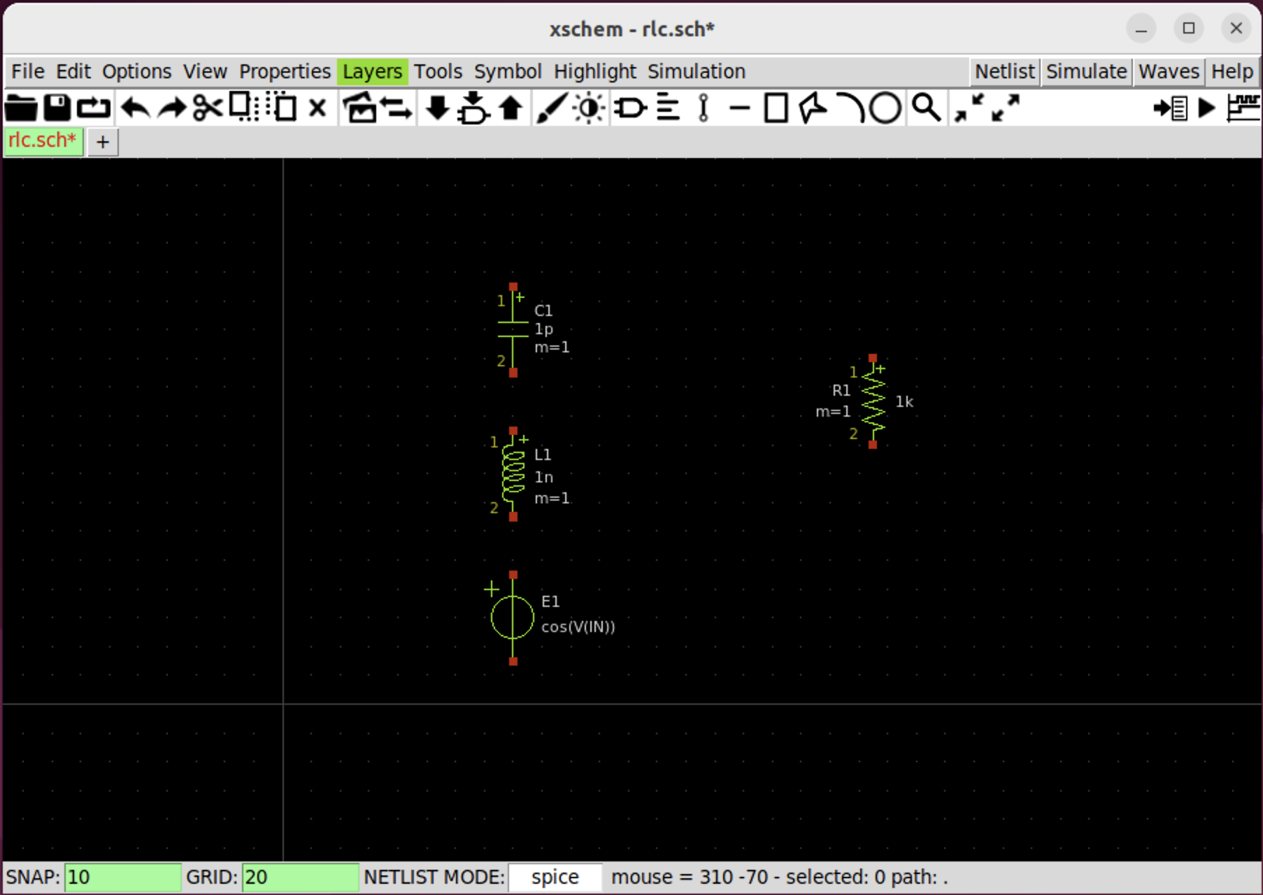
Follow the same procedure and insert the inductor, resistor and voltage source symbol.
inductor => ind.sym
resistor => res.sym
voltage source => vsource_arith.sym
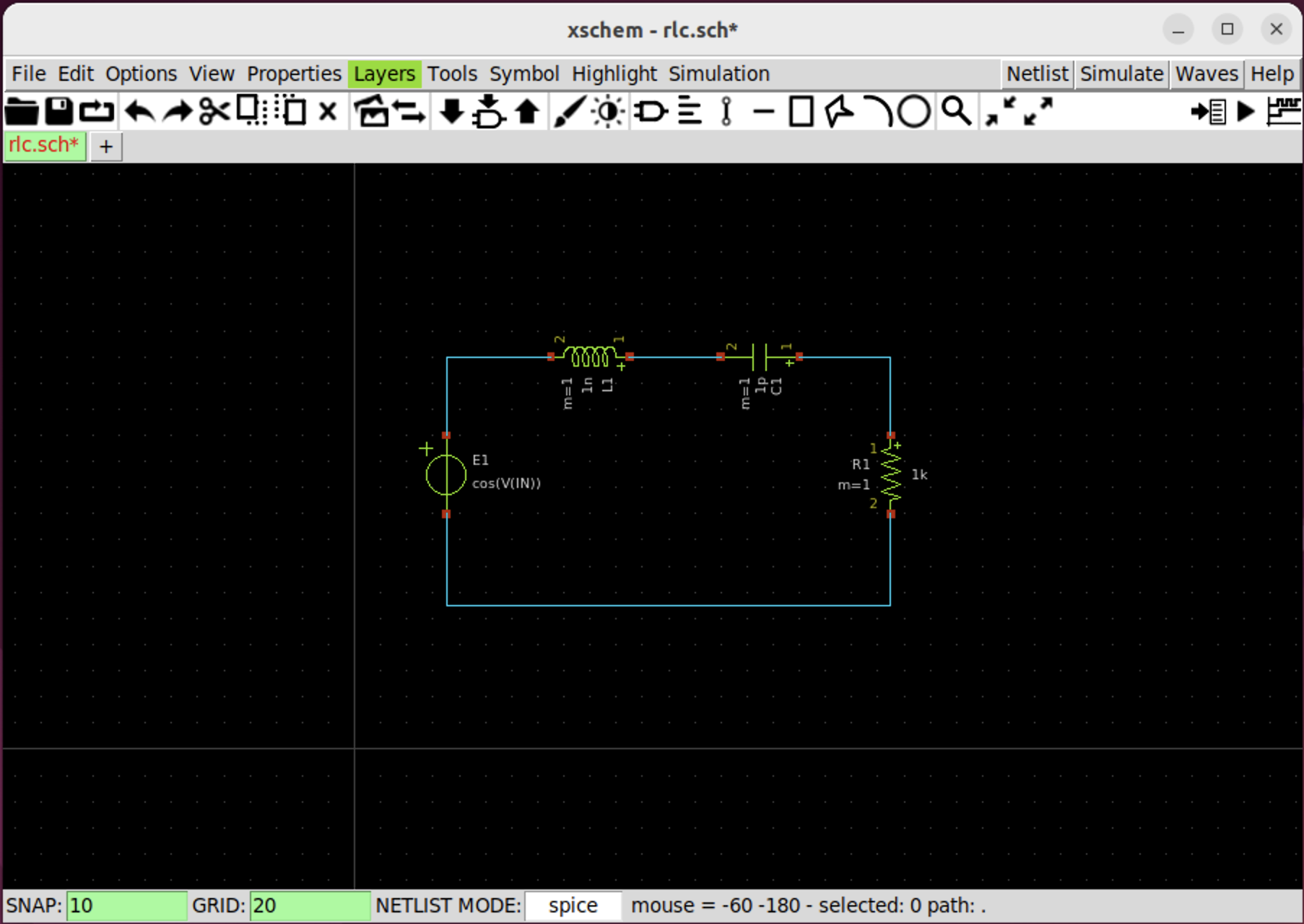
Now, we can use option+R and m key to move the component. Use w key to connect the component. Fig. 6 will become to:
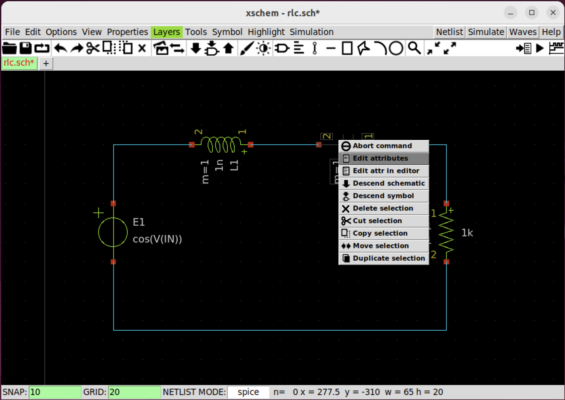
Step 3 - change component value
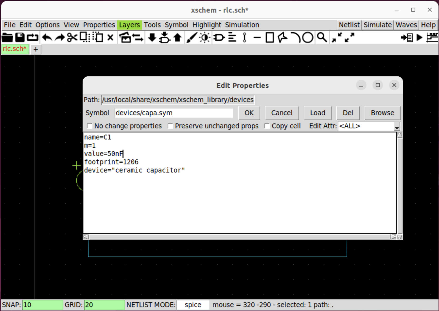
Next, select resistor and right click, then select Edit attributes option.
In the pop up window, change the capacitor value to 50nF.
Follow the same procedure and set inductor and voltage source value as shown in Fig. 10.
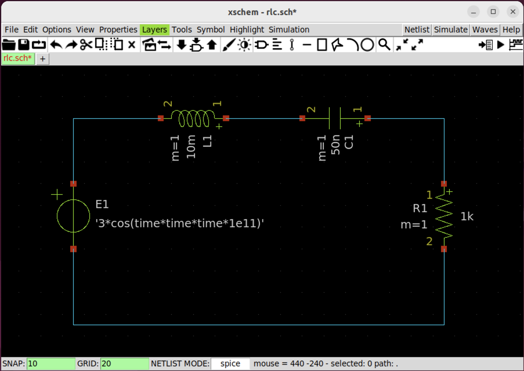
Notice, for the voltage source, set its attribute to be "'3*cos(time*time*time*1e11)'" (include quotes, single and double).
Step 4 - add label
First, insert lab_pin into the schematic.
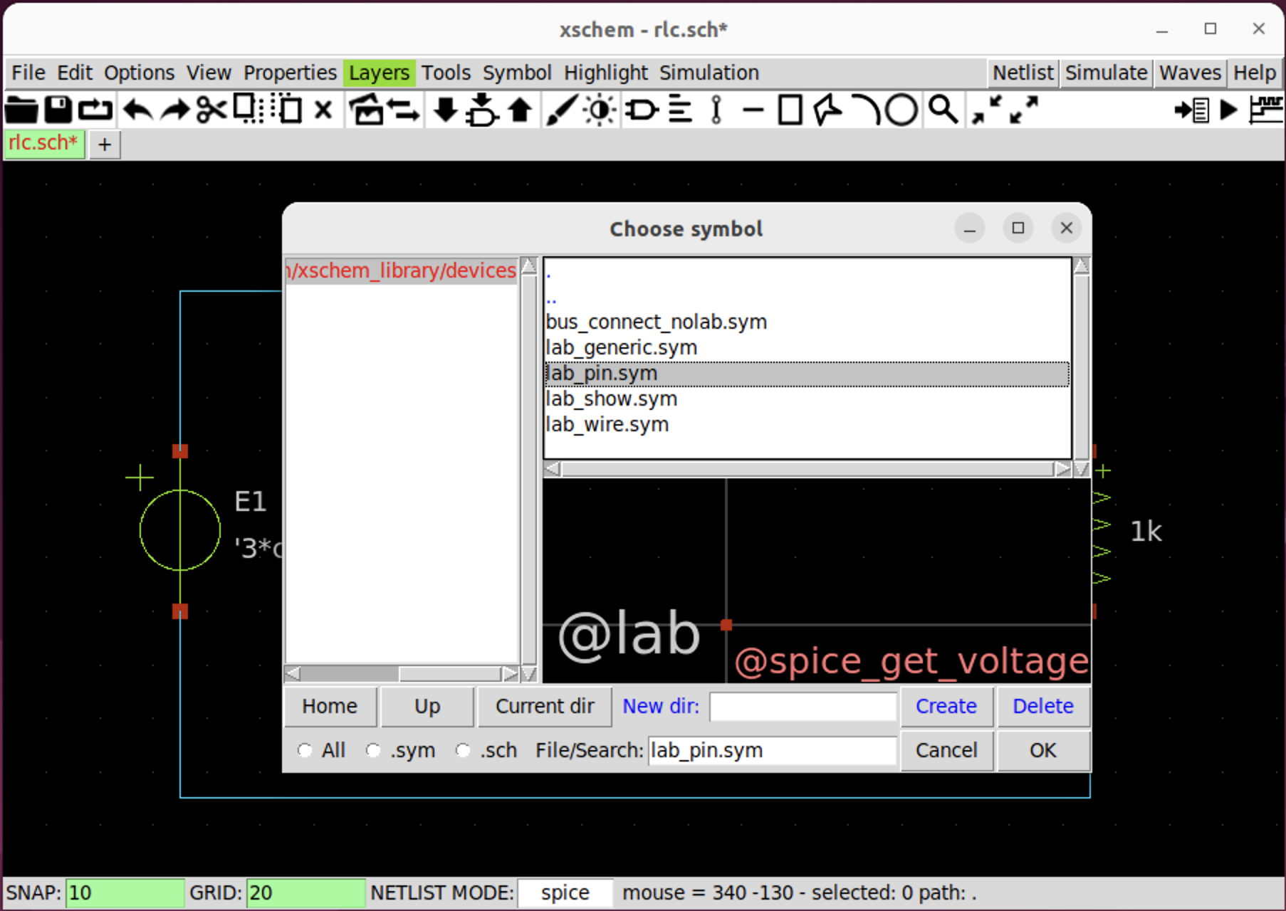
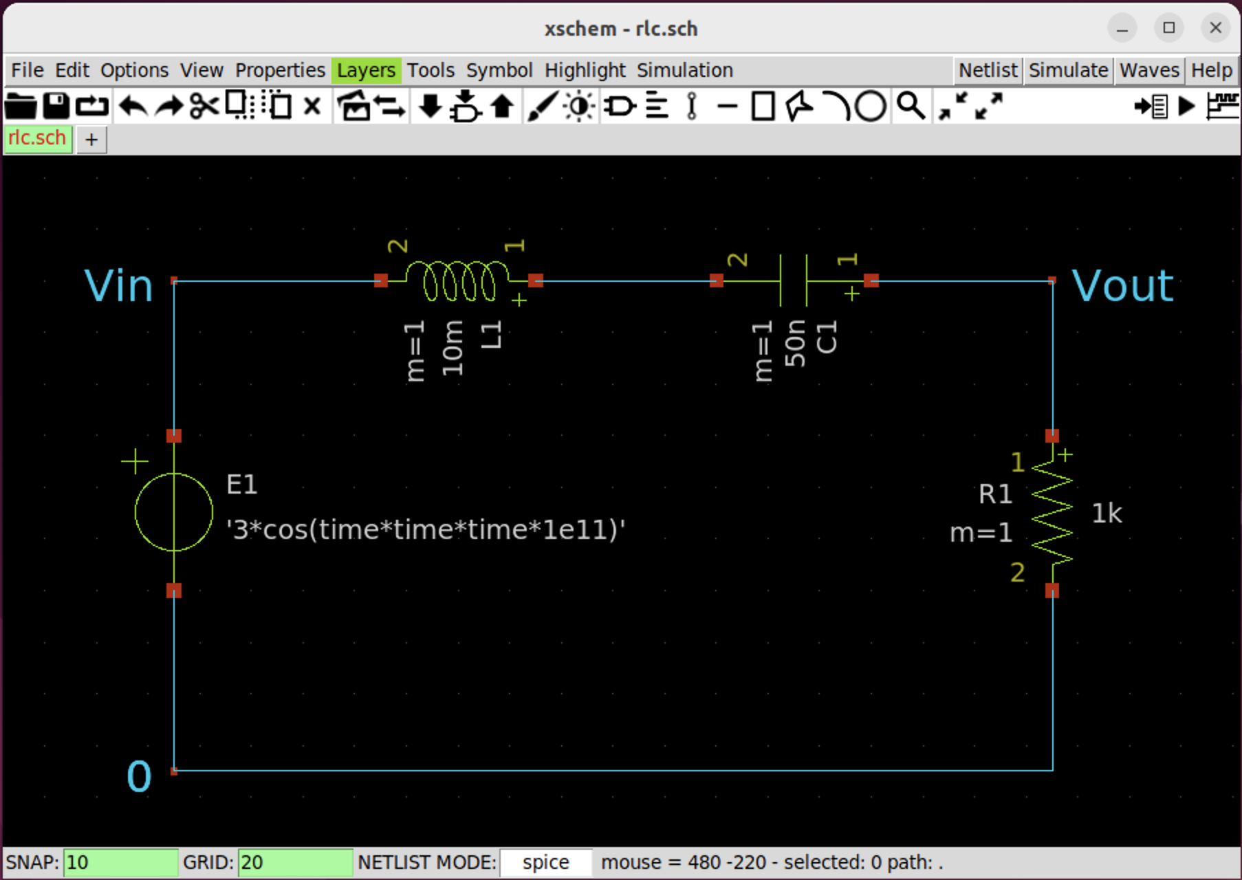
Change the attribute for each label and attach it to Vin and Vout net as shown in Fig. 12.
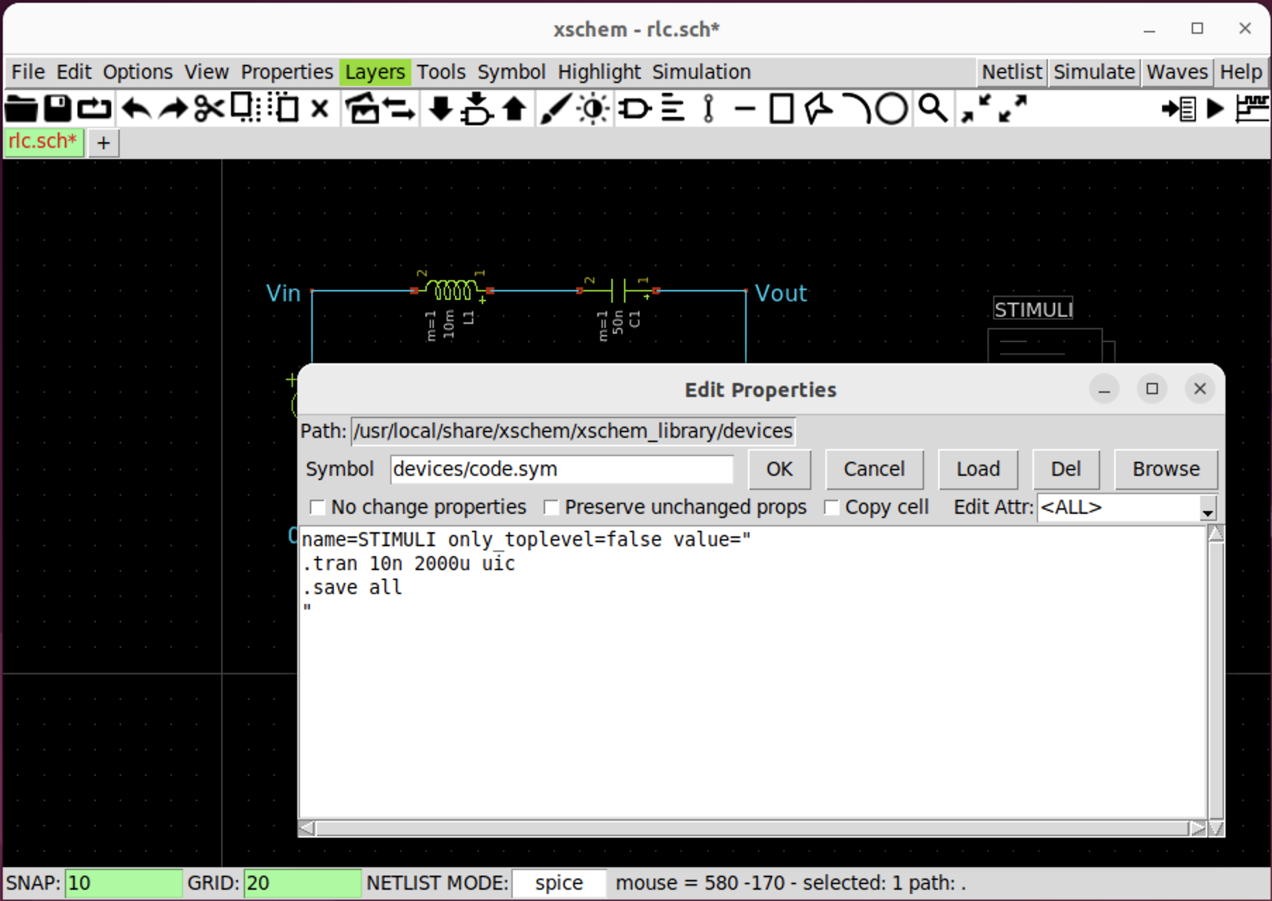
Add simulation command
Insert code.sym symbol into the schematic with the content as shown in Fig. 13.
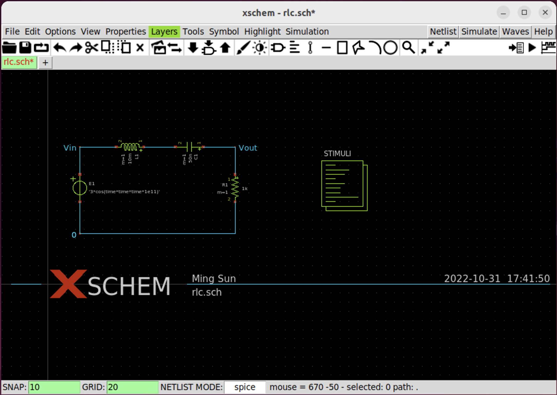
Add title block
Insert title.sym and modify its attribute. Up to this point, the schematic is completed.
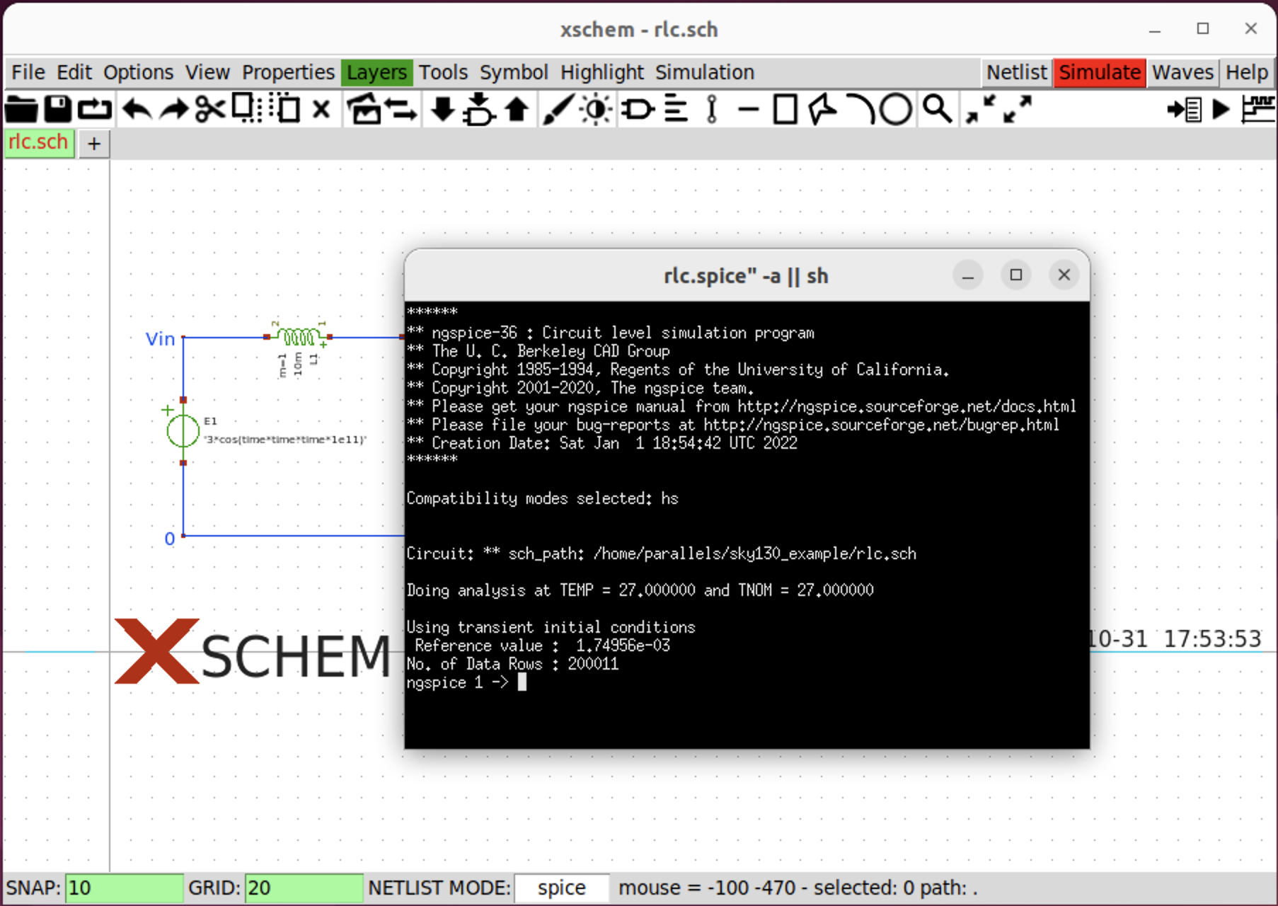
Run simulation
Click Netlist and then click Simulate. Then the Ngspice window will pop up.
In Fig. 15, I change Xschem theme to white so that it is easier to see the Ngspice pop up window. In the Ngspice pop up window, type plot Vin Vout. The waveform is shown in Fig. 16.
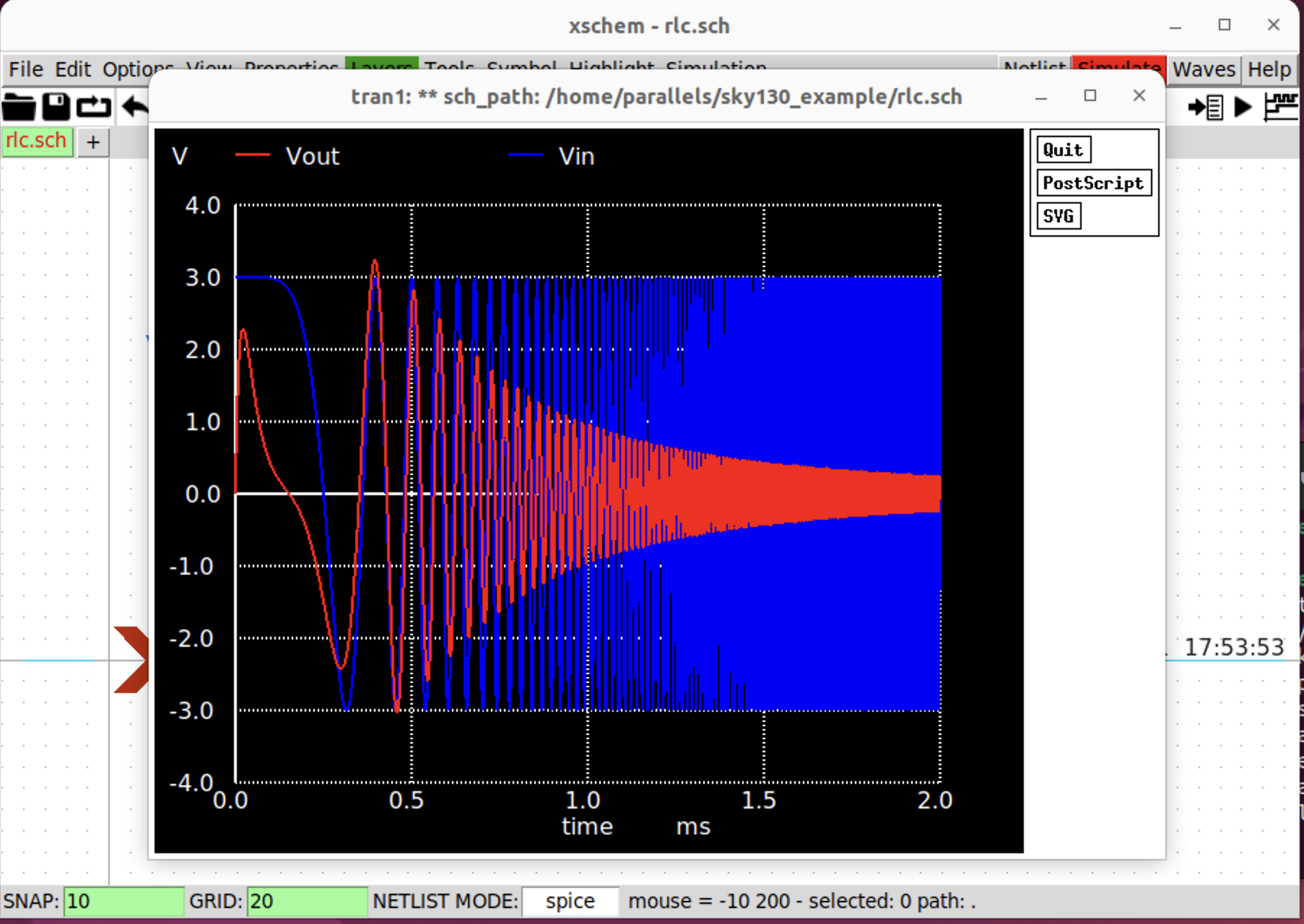
Verify the result from Matlab[2]
We can verify the Ngspice simulation result from Fig. 16 through Matlab by using the following script.
clc;clear;close all;
% component parameter
R = 1e3;
L = 10e-3;
C = 50e-9;
% time
t = linspace(0,2e-3,10000);
% Input
Vin = 3*cos(t.*t.*t*1e11);
% Transfer function
s = tf('s');
G = R/(R + s*L + 1/(s*C));
% Calculate Vout
Vout = lsim(G, Vin, t);
% Plot
plot(t*1e3, Vin, 'b', 'LineWidth',1.5);
hold on;
plot(t*1e3, Vout, 'r', 'LineWidth',1.5);
ylim([-4, 4]);
xlabel("time [ms]");
grid on;
legend(["Vin", "Vout"]);
Matlab simulation results are shown in Fig. 17.

References
[1] TUTORIAL: RUN A SIMULATION WITH XSCHEM
[4] rlc.sch download