Different type of load impact on power stage transfer function


Ming Sun / December 06, 2022
9 min read • ––– views
Resistive load
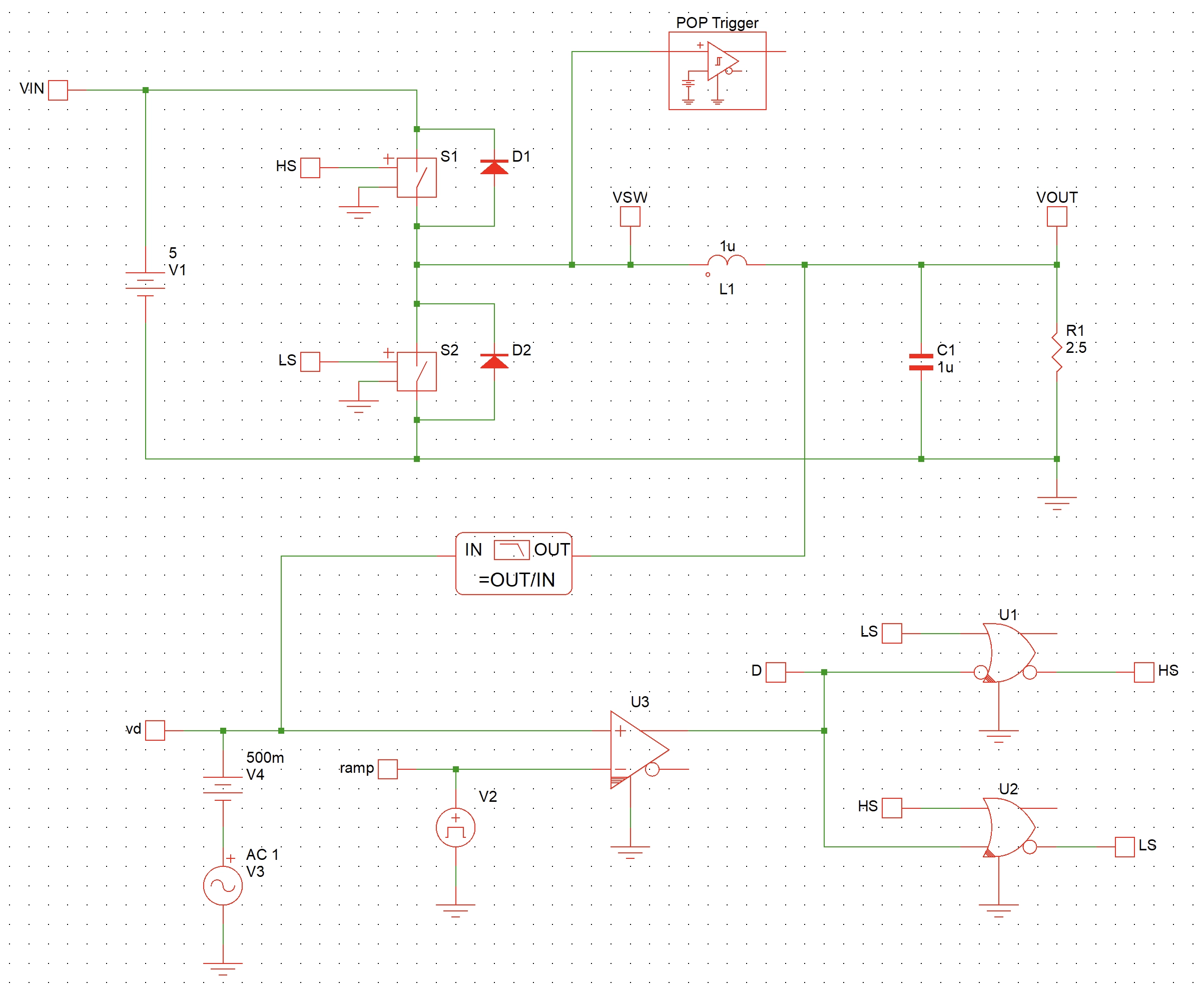
The Buck converter test bench in Simplis is as shown in Fig. 1. In Fig. 1 model, we are using resistive load at Buck converter output.

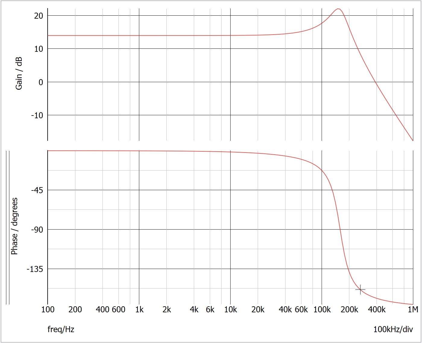
The Gvd simulation from Simplis is as shown in Fig. 2.

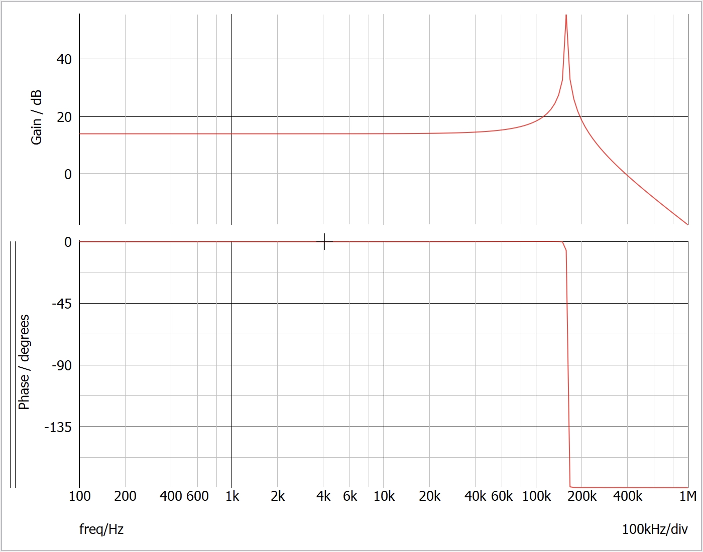
DC current source as the load
In Fig. 3 model, we are using ideal DC current source at Buck converter output.

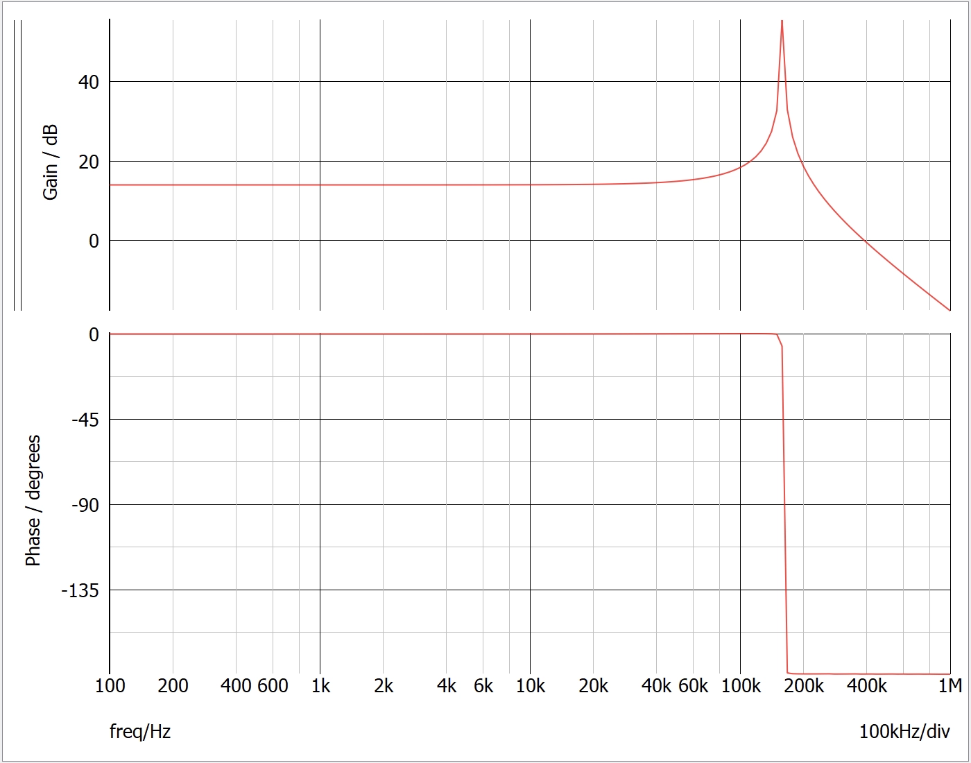
The Gvd simulation from Simplis is as shown in Fig. 4.

Active load with feedback control
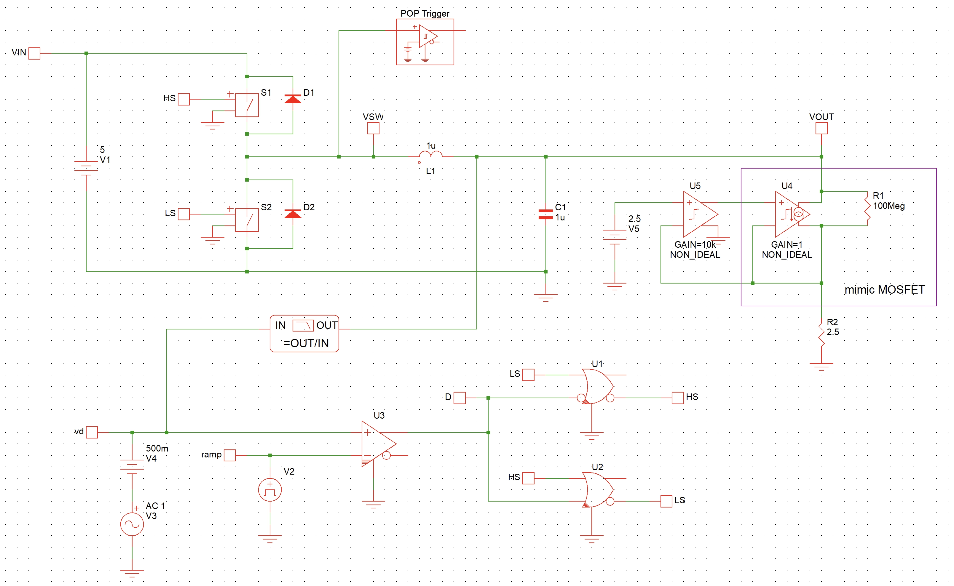
Finally, let us use an active load at Buck converter's output. Here the vcvs is to mimic an ideal Opamp. The vccs and the 100MΩ is to mimic an NMOS device.

The Gvd simulation from Simplis is as shown in Fig. 6.
Comparison
Next, we can export the data from Simplis as a csv file and plot the comparison by Matlab as shown in Fig. 7.


In Ref. [6], the Gvd transfer function is given by:
The complexed pole frequency is given by:
From Eq. 2, the complexed pole frequency is determined by the inductor value L and capacitor value C. Therefore, the type of load at Buck converter output does not impact the complexed pole frequency.
The quality factor Q impact the peaking at complexed pole frequency. The quality factor Q is given by:
From Eq. 3, we can see the loading impedance has a direct impact on the quality factor Q. In the ideal current source and active load case, ideally no matter how the VOUT changes, the current should stay the same. Therefore, the small signal output impedance is inifinity. As a result, both the ideal current source and active load shows much higher peaking than the resistive load.
Conclusion
The loading impedance does not impact the complexed pole frequency. However, it has a direct impeact on the quality factor Q. Ideal current source and active load shows a higher quality factor Q at the complexed pole frequency.
References and downloads
[1] Fundamentals of power electronics - Chapter 2
[2] Open-loop Buck converter with active load in Simplis - download
[3] Open-loop Buck converter with active load in Simplis - pdf
[4] Open-loop Buck converter with resistive load in Simplis - download
[5] Open-loop Buck converter with DC current source as the load in Simplis - download
[6] Power stage transfer function cheatsheet - Voltage Mode
[6] Power stage transfer function cheatsheet - Voltage Mode (pdf)