Filter design example


Ming Sun / December 25, 2022
9 min read • ––– views
Background
The techniques described in this blog post is based on the class and materials taught by Prof. Hongjiang Song at ASU EEE598 Serial link class. Please refer to Ref. [1] for more detailed information about the class.
Design target
The design target is to use the above techniques to design a circuit which will have the following transfer function:
Building blocks
In this section, we are going to make several building blocks with active-RC circuit.
- Integrator G. Let us first make an integrator building block with the following transfer function:
Fig. 1 shows an integrator by using the active RC circuit.

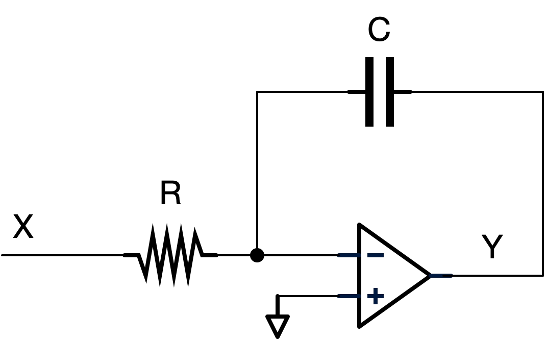
Let us try to derive the transfer function for Fig. 1. We have:
Therefore, we have:
Where,
- Adder. Fig. 2 shows an adder created by the active RC circuit.

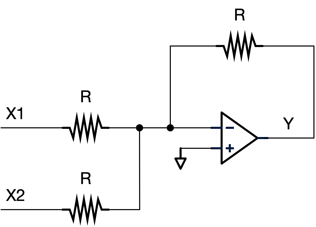
From Fig. 2, we have:
Therefore,
- Scaler. Fig. 3 shows an scaler (gain block) created by the active RC circuit.

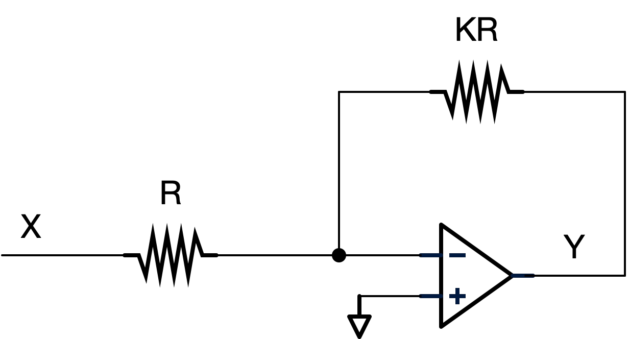
From Fig. 3, we have:
Therefore, we have:
Filter design based on signal flow chart
By combining Eq. 1 and Eq. 2, we have:
Eq. 10 can be rewritten as:
Or,
Eq. 12 can be further written as:
The signal flow chart can be drawn based on Eq. 13, which is as shown in Fig. 4.


From Fig. 4, we have:
Which matches exactly with Eq. 13.
Since we have three basic building blocks (integrator, adder and scaler), Fig. 4 can be re-drawn as:


Let us pick R=100kΩ and C=100pF. As a result,
Verification
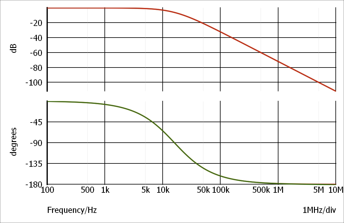
The test bench is as shown in Fig. 6. We have an active RC circuit and a Laplace transfer function block so that we can compare the Bode plot between the actual circuits and the Math equations.

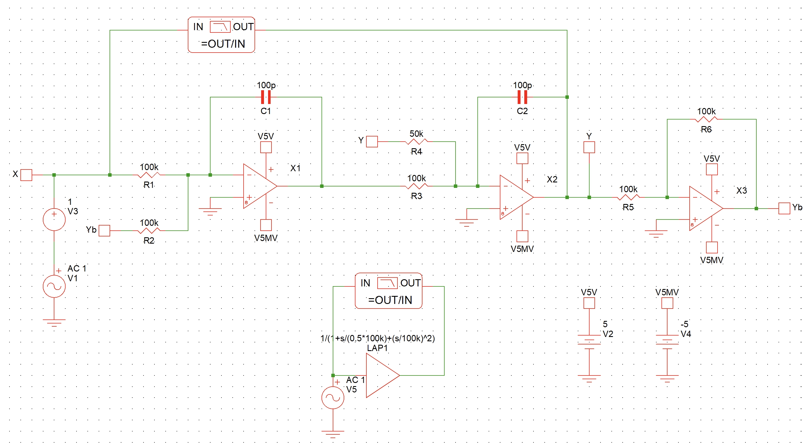
The Bode plot from SIMetrix AC simulation is as shown in Fig. 7.

References and downloads
[1] EEE598 - by Prof. Hongjiang Song
[3] Prof. Hongjiang Song's LinkedIn