Inductor current and Vout ripple plot in Simplis


Ming Sun / December 06, 2022
9 min read • ––– views
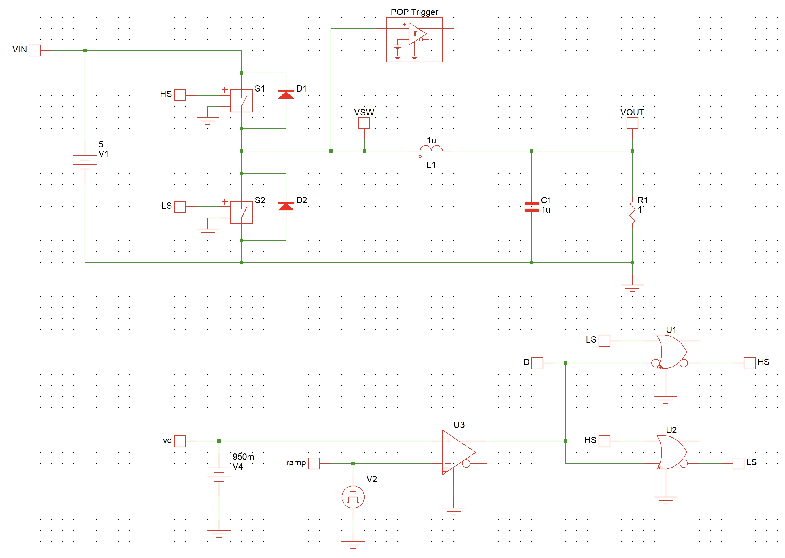
Buck converter
The Buck converter test bench in Simplis is as shown in Fig. 1.

The Matlab script for plotting the inductor current and Vout ripple is as shown below.
clc; clear; close all;

d = linspace(0.05,0.95,19)*100;

ind_ripple = [242.96164, 457.42, 647.83, 813.73, 954.708, 1070.425, ...
    1160.6, 1225.02, 1263.5214, 1276.02, 1262.4826, 1222.9423, ...
    1157.4937, 1066.2943, 949.5636, 807.584, 640.7, 449.32, 233.9115];

vout_ripple = [30.5, 57.31, 81.026, 101.62, 119.073, 133.3658, ...
    144.4838, 152.4152, 157.1518, 158.69, 157.02, 152.16, ...
    144.1012, 132.8564, 118.4372, 100.8589, 80.14, 56.302, 29.3697];

yyaxis('left');
plot(d, ind_ripple, 'LineWidth',2);
grid on;
xlabel("Duty cycle [%]");
ylabel("Inductor current ripple [mA]");

yyaxis('right');
plot(d, vout_ripple, 'LineWidth',2);
ylabel("Vout ripple [mV]");
The plot is as shown in Fig. 2. From Fig. 2, we can easily tell that the worst case ripple happens at D=50% both inductor current and Vout ripple.


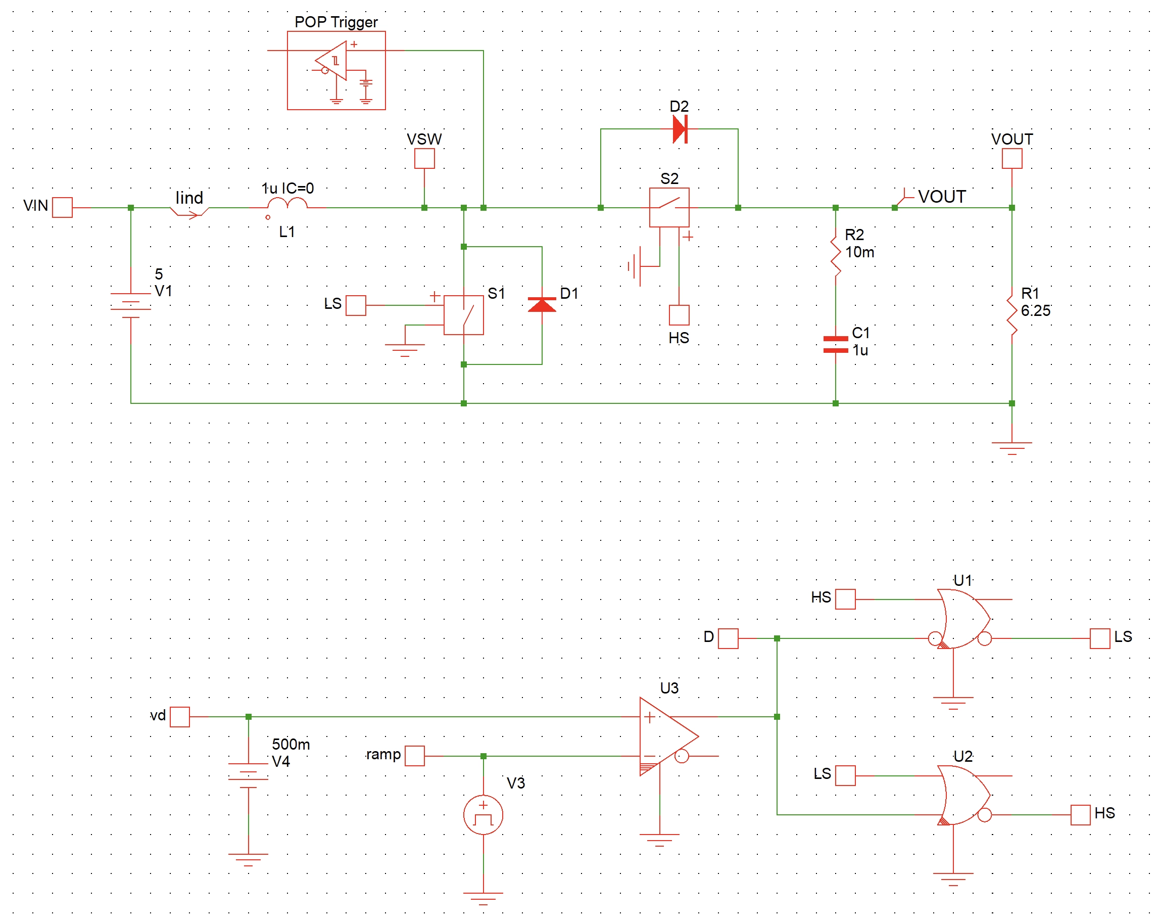
Boost converter
The Buck converter test bench in Simplis is as shown in Fig. 3.

The Matlab script for plotting the inductor current and Vout ripple of Boost converter is as shown below.
clc; clear; close all;

d = [10,20,30,40,50,60,65,70, 75, 80,85,90];

ind_ripple = [0.5, 1.0, 1.5, 1.999, 2.498, 2.99705,3.2458, ...
    3.4939,3.740548, 3.984266, 4.220402, 4.430376];

vout_ripple = [119.4992, 235.8, 368.6863, 541.8773, 805.18, 1214.823, ...
    1510.357, 1907.425, 2468.228, 3318.632, 4756.799, 7693.655];

yyaxis('left');
plot(d, ind_ripple, 'LineWidth',2);
grid on;
xlabel("Duty cycle [%]");
ylabel("Inductor current ripple [A]");

yyaxis('right');
plot(d, vout_ripple, 'LineWidth',2);
ylabel("Vout ripple [mV]");
The plot is as shown in Fig. 4. From Fig. 4, we can easily tell that the worst case ripple happens at D=100% both inductor current and Vout ripple.

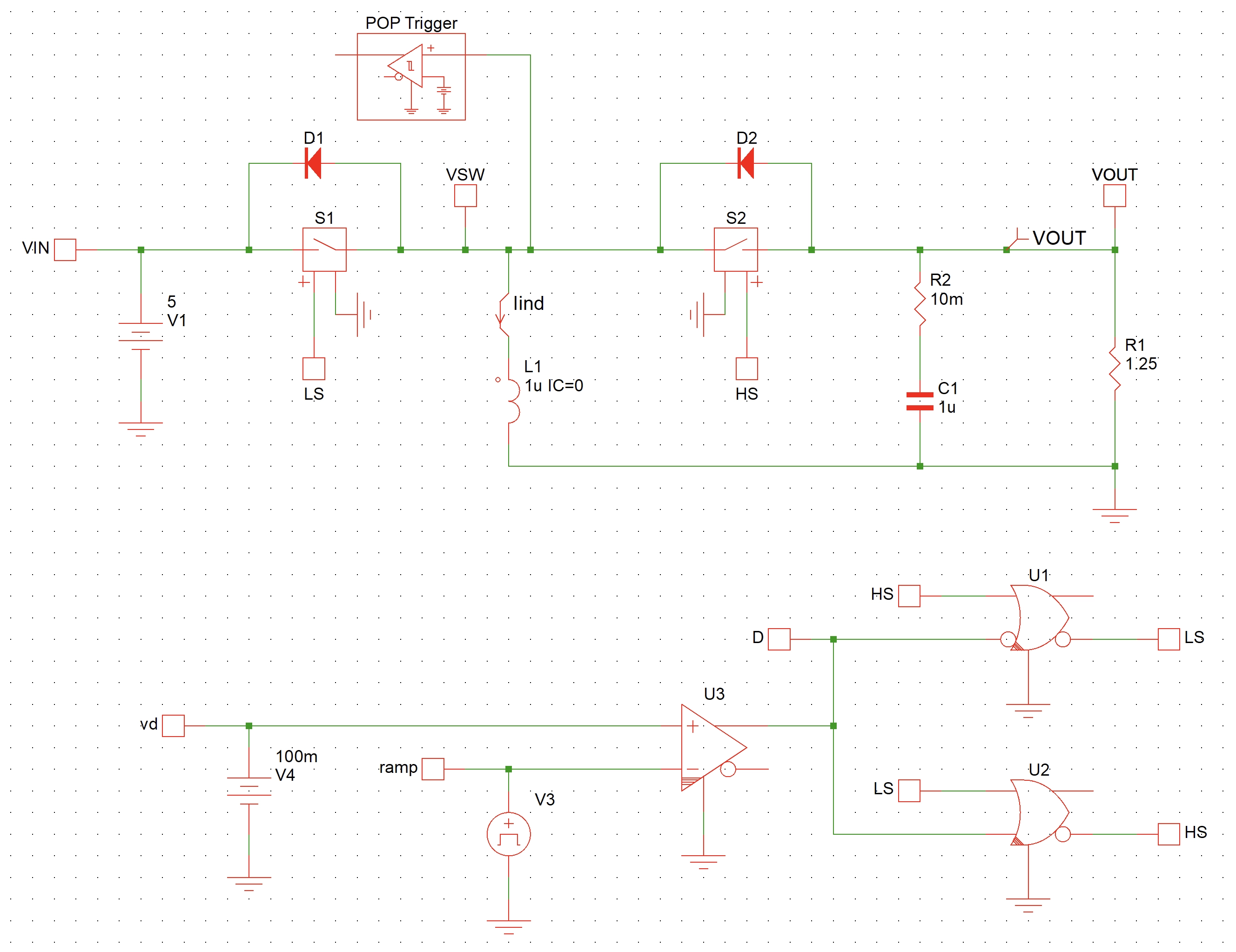
IBB converter
The IBB converter test bench in Simplis is as shown in Fig. 5.

The Matlab script for plotting the inductor current and Vout ripple of IBB converter is as shown below.
clc; clear; close all;

d = [10,20,30,40,50,60,65,70, 75, 80,85,90];

ind_ripple = [0.5, 1.0, 1.5, 1.999, 2.498, 2.99705,3.2458, ...
    3.4939,3.740548, 3.984266, 4.220402, 4.430376];

vout_ripple = [119.4992, 235.8, 368.6863, 541.8773, 805.18, 1214.823, ...
    1510.357, 1907.425, 2468.228, 3318.632, 4756.799, 7693.655];

yyaxis('left');
plot(d, ind_ripple, 'LineWidth',2);
grid on;
xlabel("Duty cycle [%]");
ylabel("Inductor current ripple [A]");

yyaxis('right');
plot(d, vout_ripple, 'LineWidth',2);
ylabel("Vout ripple [mV]");
The plot is as shown in Fig. 6. From Fig. 6, we can easily tell that the worst case ripple happens at D=100% both inductor current and Vout ripple.

Conclusion
For Buck converter, the worst case ripple happens at 50% duty cycle case.
For Boost and IBB converter, the worst case ripple happens at 100% duty cycle case.
References and downloads
[1] Fundamentals of power electronics - Chapter 2
[2] Simplis test bench for Buck converter - download