Simulation of capacitance in Xschem


Ming Sun / November 07, 2022
6 min read • ––– views
Schematic
The following components from Skywater130 PDK are used in this simulation:
cap_mim_m3_2.sym: mim capcap_var_lvt.sym: varactor capnfet_01v8_lvt.sym: 1.8V LVT NMOS
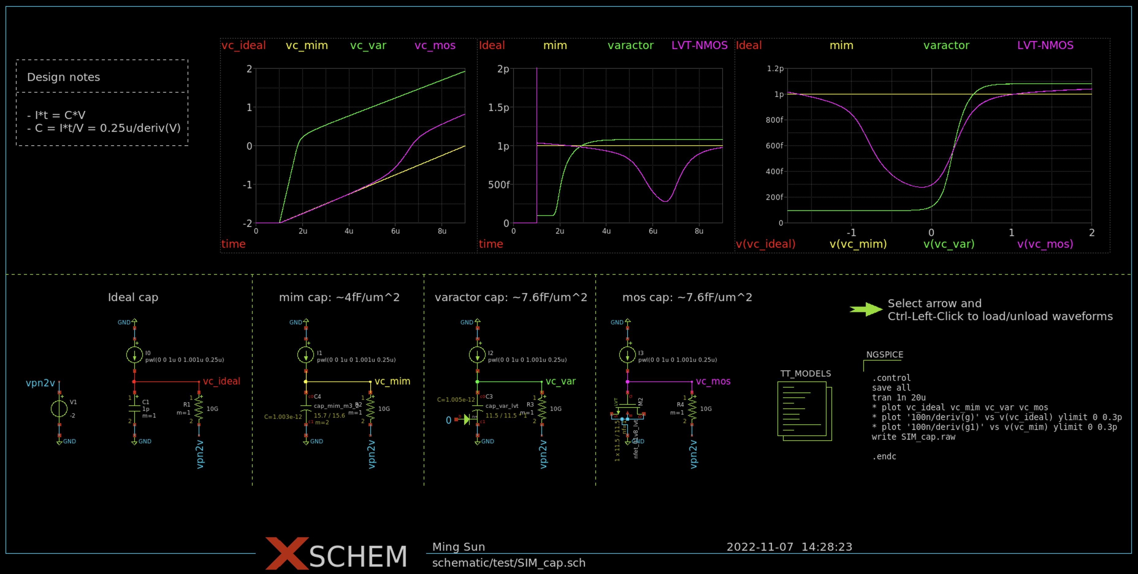
The end goal is to compare the effective capacitance of mim cap, varactor cap and 1.8V LVT NMOS cap with an ideal capacitor.
The completed schematic is as shown in Fig. 1.

Theory
For a capacitor, we have:
Eq. (1) can be rewritten as:
Where,
From Eq. (2)~(3), to simulate the effective capacitance of mim, varator and MOSFET, the idea is that we source (inject) a constant current into its gate. From the simulation, we plot the corresponding gate voltage. Then we take the derivative of the gate voltage. The effective capacitance can be found out through Eq. (2) afterwards.
Components used in schematic
The following are some key components and the corresponding properties used in the SIM_cap.sch test bench.
isource.sym: current pwl fromxschem_library/devices.
name=I0 value="pwl(0 0 1u 0 1.001u 0.25u)"
code_shown.sym: stimulus
name=NGSPICE
only_toplevel=true
value="
.control
save all
tran 1n 10u
* plot vc_ideal vc_mim vc_var vc_mos
* plot '100n/deriv(g)' vs v(vc_ideal) ylimit 0 0.3p
* plot '100n/deriv(g1)' vs v(vc_mim) ylimit 0 0.3p
write SIM_cap.raw

.endc
"
launcher.sym: load/unload simulation data into waveform graph
name=h1
descr="Select arrow and
Ctrl-Left-Click to load/unload waveforms"
tclcommand="
xschem raw_read $netlist_dir/[file tail [file rootname [xschem get current_name]]].raw tran
"
waveform graph: waveform viewer.
"Ideal; 0.25e-6 vc_ideal deriv0() /"
"mim; 0.25e-6 vc_mim deriv0() /"
"varactor; 0.25e-6 vc_var deriv0() /"
"LVT-NMOS; 0.25e-6 vc_mos deriv0() /"

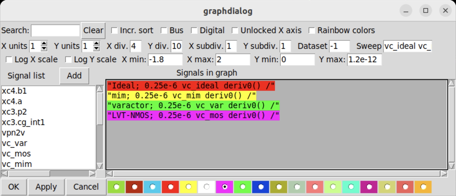
Notice that in the Sweep properties, we have to set the corresponding voltage so that we can have the plot of capaictance vs. gate voltage.
vc_ideal vc_mim vc_var vc_mos
Conclusion
mimcap basically have the same capacitance behavior as the ideal cap. This is expected sincemimis the effective capacitance of between metal layers.varactor: varactor cap is majority carrier device. Varactor cap can reach to its full capacitance with~500mVgate voltage.LVT-NMOS: in order to reach to the full capacitance, the gate voltage has to be sufficiently high so that the inversion layer can be formed beneath the gate.
Cap density
mim: 4.1µF/mm2
varactor: 8.2µF/mm2
1.8V LVT NMOS: 7.9µF/mm2