Open loop Boost converter modeling in Simulink


Ming Sun / November 28, 2022
7 min read • ––– views
Block diagram
The Boost converter power stage block diagram is shown in Fig. 1.


Equations
In order to create the model in Matlab, we have to derive equations first. For a Boost converter inductor, we have the following:
Where,
Eq. 1 can be simplified as:
Where,
Eq. 4 can be rewritten as:
For the output capacitor, we have the following:
Eq. 6 can be rewritten as:
Simulink modeling
The overall process to model the open loop Boost converter is similar as the open loop Buck converter modeling as described in Ref. [2].
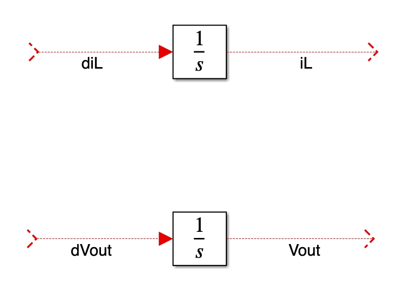
- First, let us import to
integratorinto the simulink cavans as shown in Fig. 2.

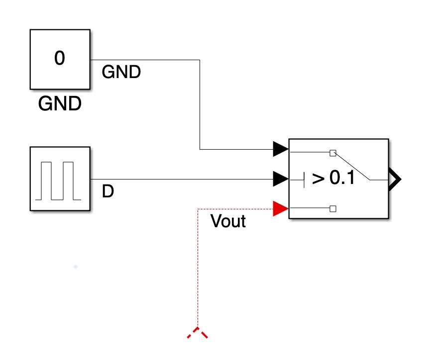
- To mimic the switching behavior on the
VSWnet, we will use aswitch. Fig. 2 shows the connections. Basically, when duty cycleDis greater than0.1,VSWis connected to ground and whileDis less than0.1,VSWis connected toVout. This is exactly the switching behavior for a Boost converter.

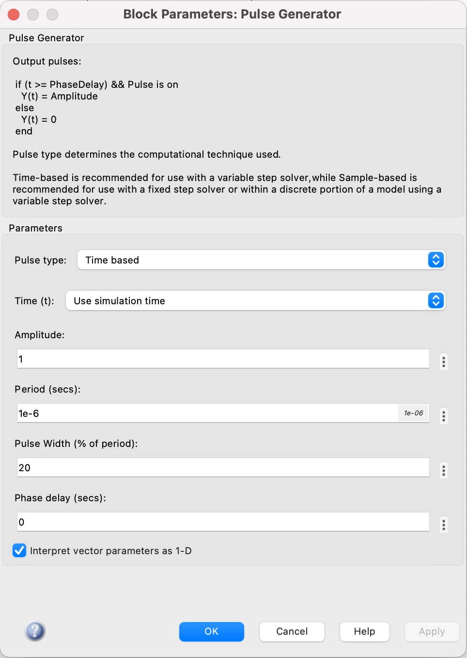
The setting of the pulse generator is as shown in Fig. 4.

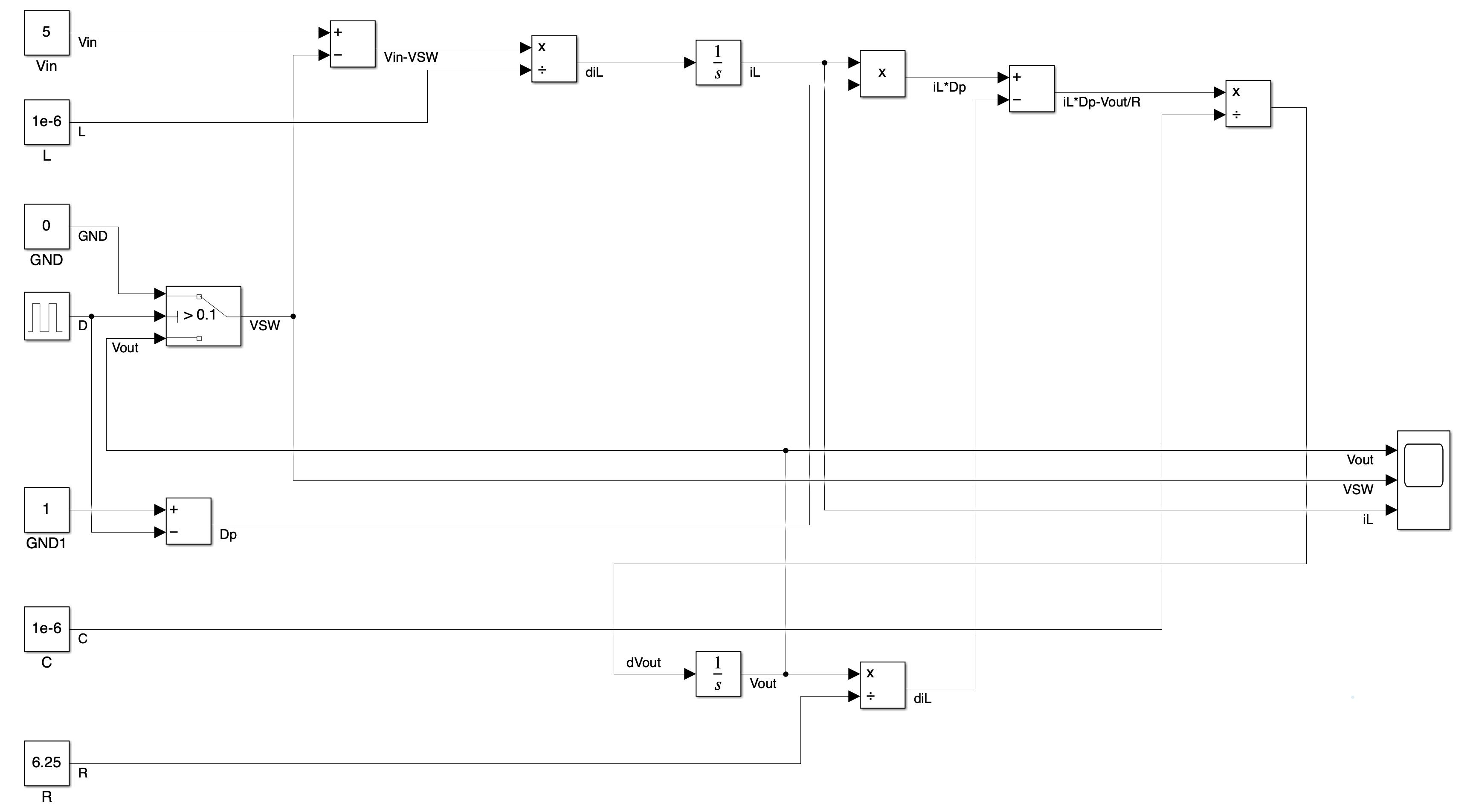
Since the overall process to build this Boost converter open loop model is similar of the process for the Buck converter, please refer to Ref. [2] if you are not familiar with the process. The completed open loop Boost converter model in Simulink is as shown in Fig. 5.

Simulation results
We know for a given Boost converter with 5Vin and 20% duty cycle, its output can be calculated as:
The simulation results from simulink are as shown in Fig. 6.

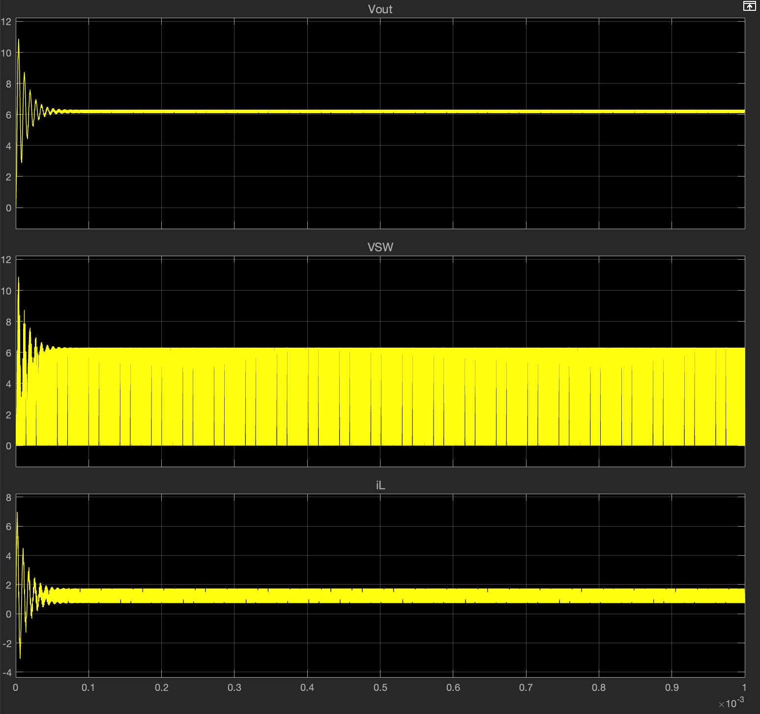
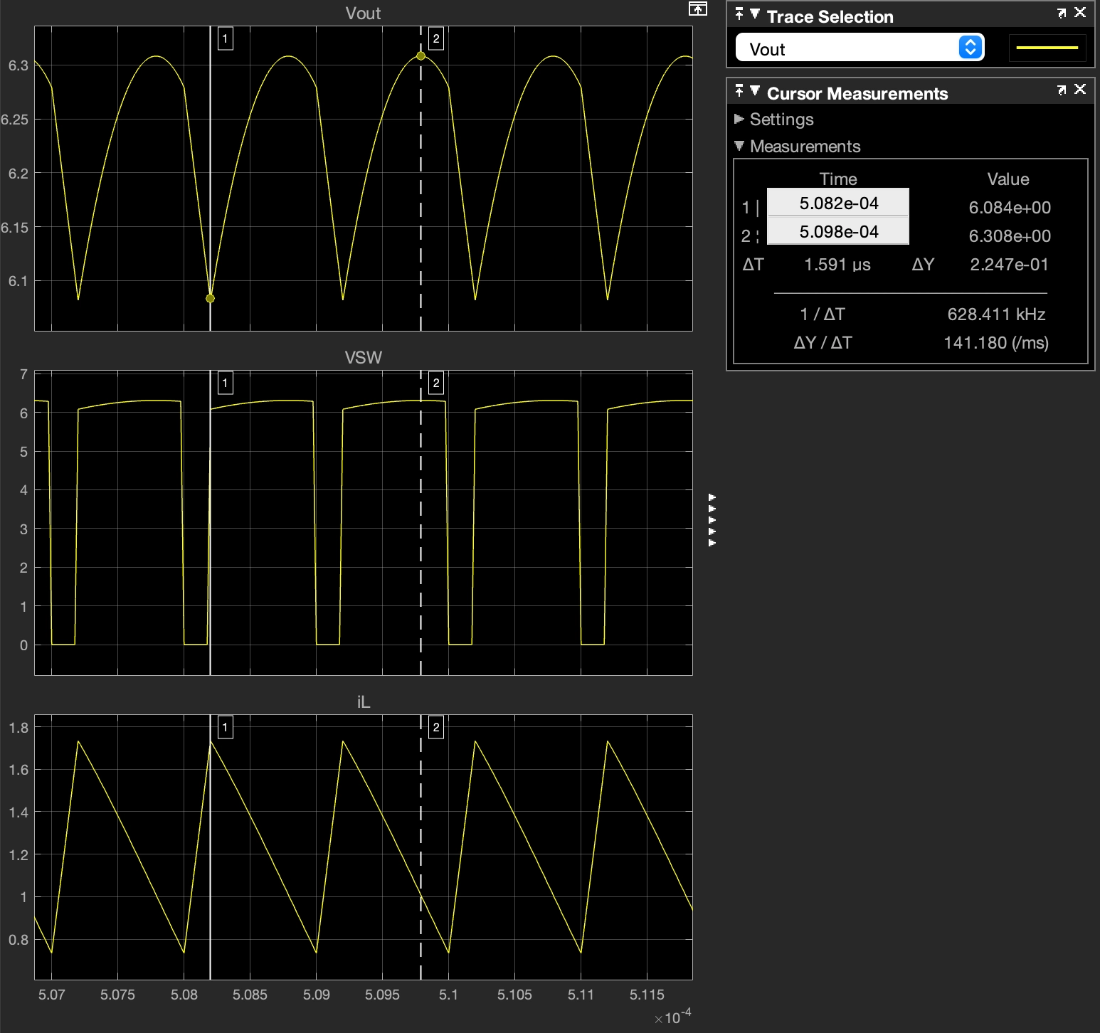
Fig. 7 shows the zoom-in waveforms. We can see that the Vout average voltage meets our expectation.
References and materials
[1] Fundamentals of power electronics - Chapter 2
[2] Simulation of open-loop Buck converter in Simulink