Simulation of open-loop Buck converter in Simulink


Ming Sun / November 17, 2022
6 min read • ––– views
In Ref. [1], we built a simple open-loop Buck converter in Xscheme. In this tutorial, we are going to create a simple open-loop Buck converter in Matlab.
Equations
In order to create the model in Matlab, we have to derive equations first. For a Buck converter inductor, we have the following:
For the output capacitor, we have:
Eq. 1 can be rearranged as:
Eq. 2 can be rearranged as:
Simulink modeling
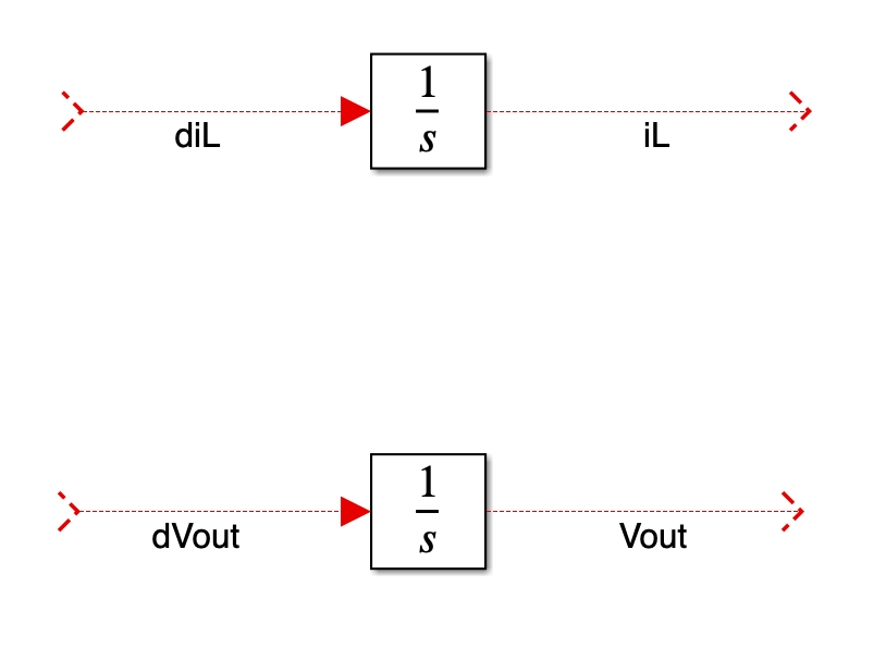
- Next we are going to use Simulink to implement Eq. 1 and Eq. 2. First, let us import to
integratorinto the simulink cavans as shown in Fig. 1.

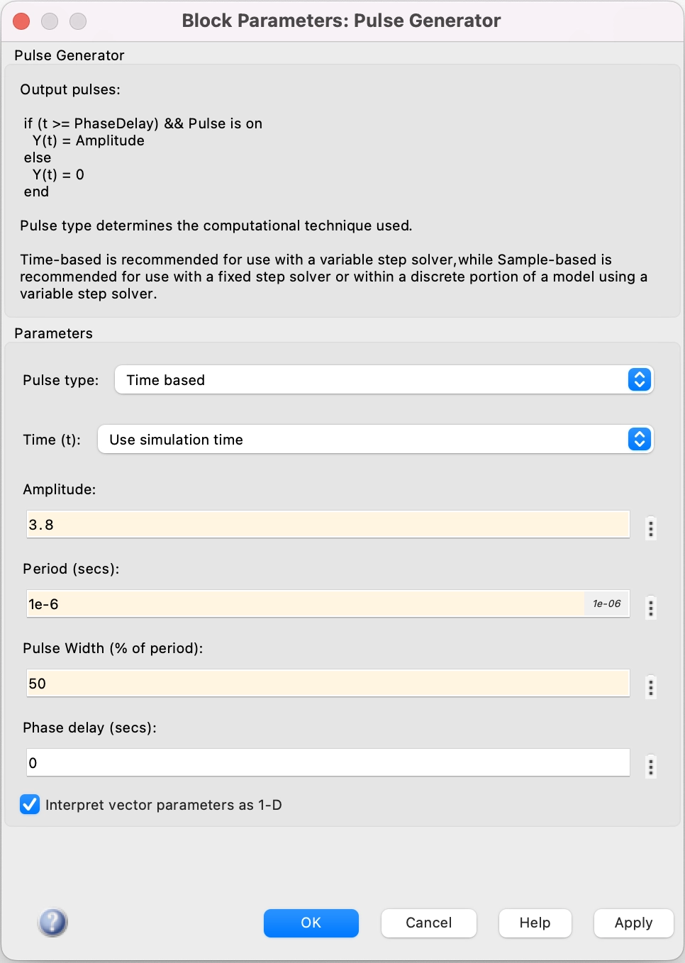
- To mimic the switching behavior on the
VSWnet, we will use apulse generator. Fig. 2 shows the settings of the pulse generator. The amplitude is set to be 3.8, which representsVin=3.8V. The duty cycle is set to be 0.5, which represents 50% duty cycle of the Buck converter controlD.

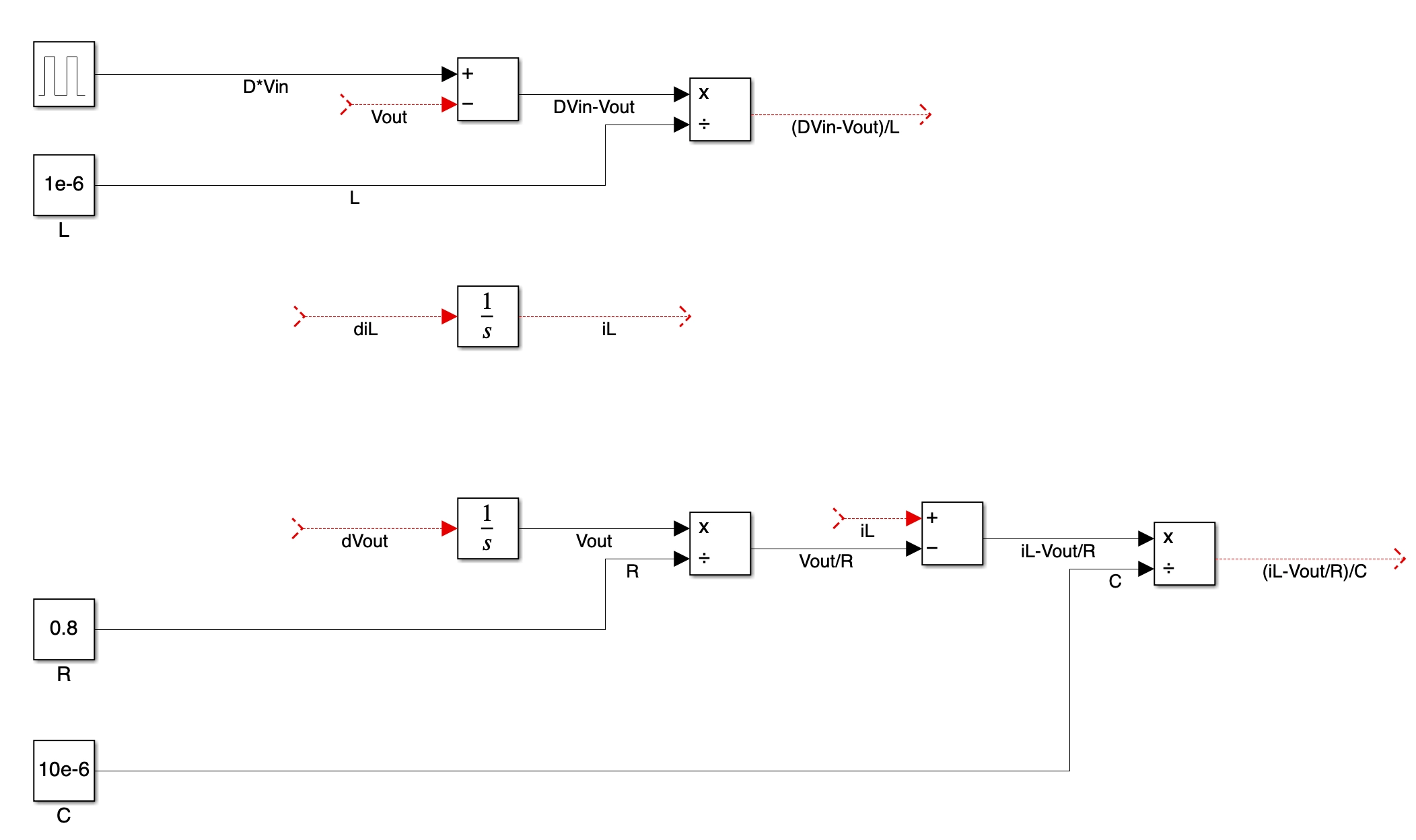
- Add product, divide and subtract block. Basically, we are preparing the model as required by Eq. 3 and Eq. 4.

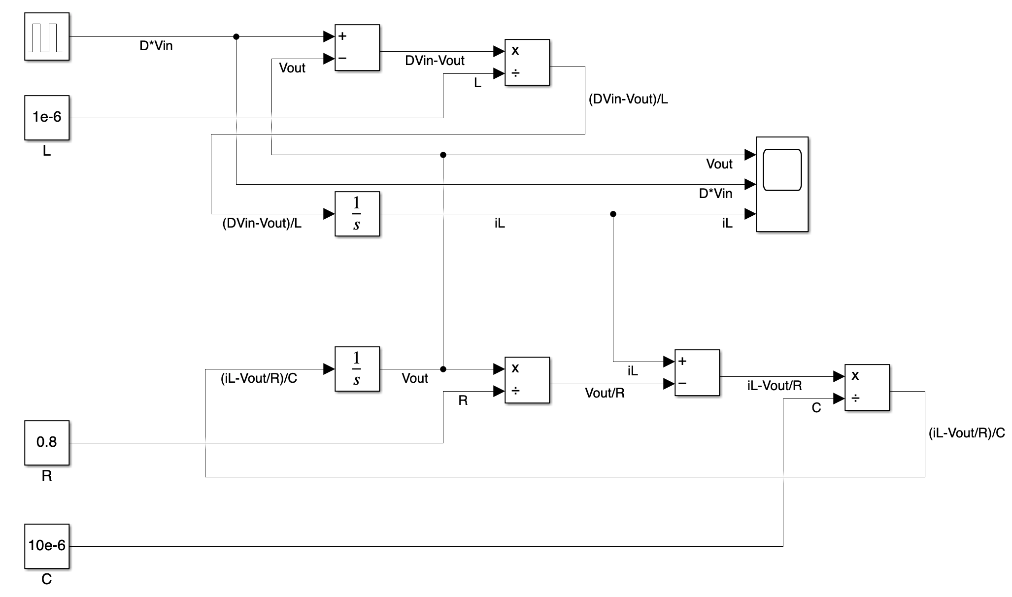
- Finished model is as shown in Fig. 4.

Simulation
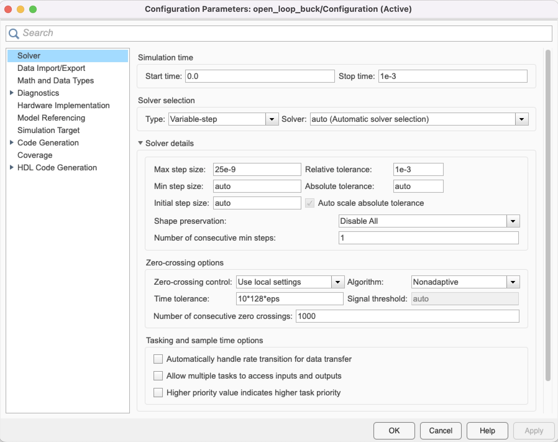
Finally, we can run the model. Before we do so, let us change the simulation time to 1ms as shown in Fig. 5.

Also, we need to constrain the max step size as well. In my setting, I set the max step size to be 25ns, which means within a switching period, simulink has to have at least 40 simulation points.

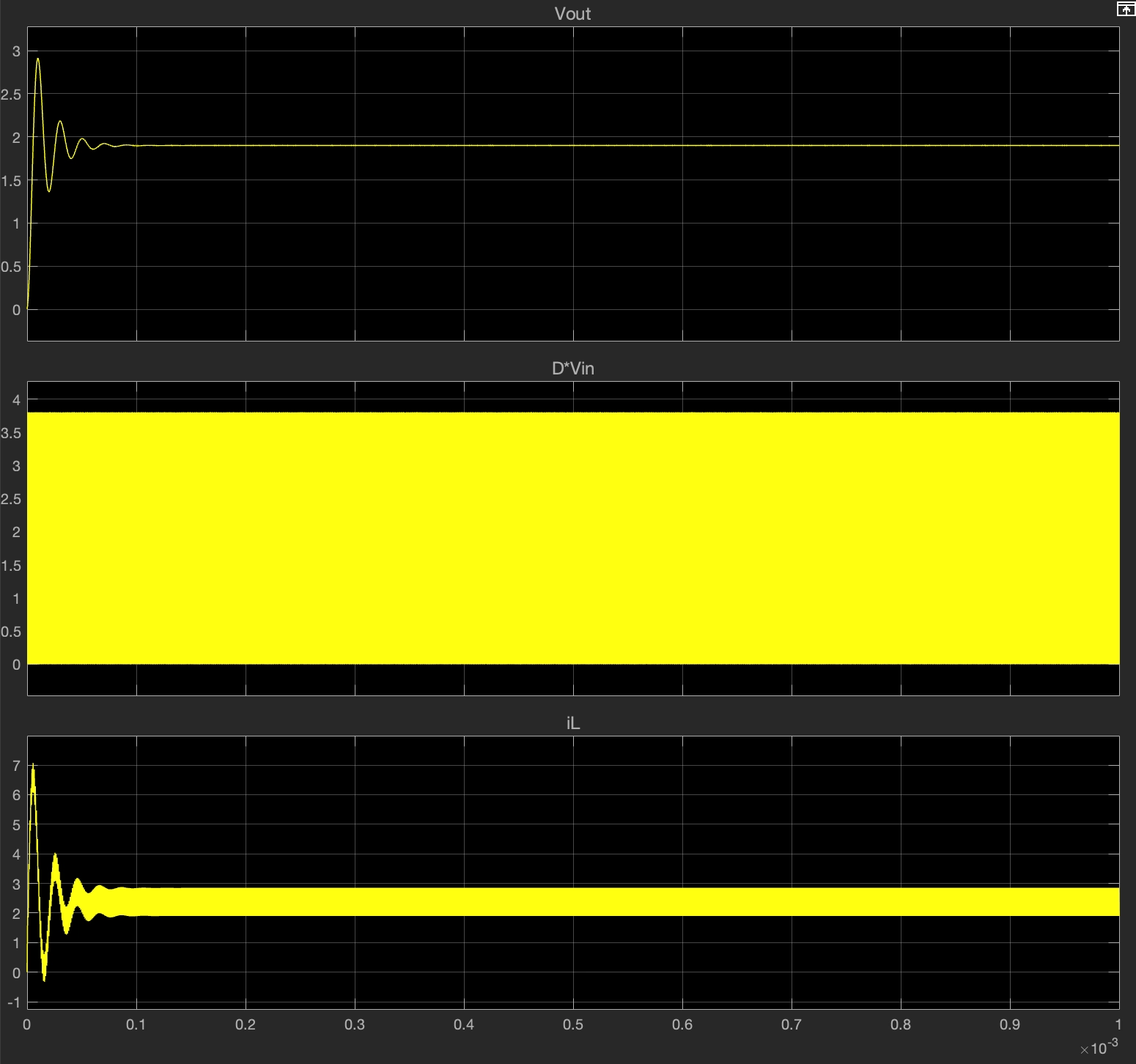
The simulation results are as shown in Fig. 7.

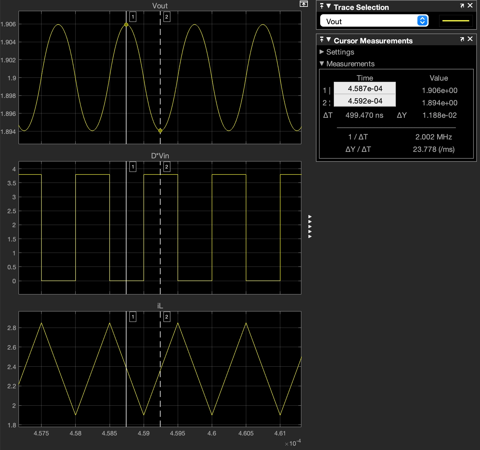
Zoomed-in waveform is as shown in Fig. 8.
References and materials
[1] Simulation of open-loop switching regulators in Xschem
[2] Matlab self-paced online course