Power stage transfer function derivations


Ming Sun / October 27, 2022
6 min read • ––– views
Step 1 - construct small-signal equations


Voltage-second balance equation
Fig. 1 shows a non-synchronous Buck power stage, where it contains a switch S1 and a free wheeling diode D1.
For the inductor, we can write the voltage-second balance as[1]:
Where, I is the inductor current and V is Buck converter's output voltage Vout. Next, let us perturb and linearize Eq. 1 by introducting the small signal perturbation as:
Here we are trying to derive the transfer function of Gvd. As a result, we can assume Vg is constant. Removing the DC terms from Eq. 2, we have:
Eq. 3 can be written in s domain as:
charge balance equation
For the capacitor, we can write the charge balance as[1]:
Next, let us perturb and linearize Eq. 5 by introducting the small signal perturbation as:
Removing the DC terms from Eq. 6, we have:
Eq. 7 can be written in s domain as:
Step 2 - solve the Gvd in Matlab
The Matlab script used to derive the Gvd transfer function is as shown below:
clc; clear; close all;

syms s
syms v i d
syms R L C Vg
syms Gvd

eqn1 = s*L*i == d*Vg - v;
eqn2 = s*C*v == i - v/R;
eqn3 = Gvd == v/d;

results = solve(eqn1, eqn2, eqn3, [v i Gvd])

Gvd = simplify(results.Gvd)
Fig. 2 shows the Gvd derived result from Matlab.

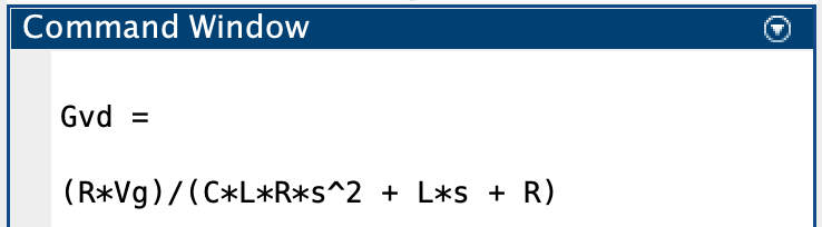
From Fig. 2, we have:
Compared with the Gvd transfer function we previously derived in the averaged switch model blog post[3], the result matches with each other.
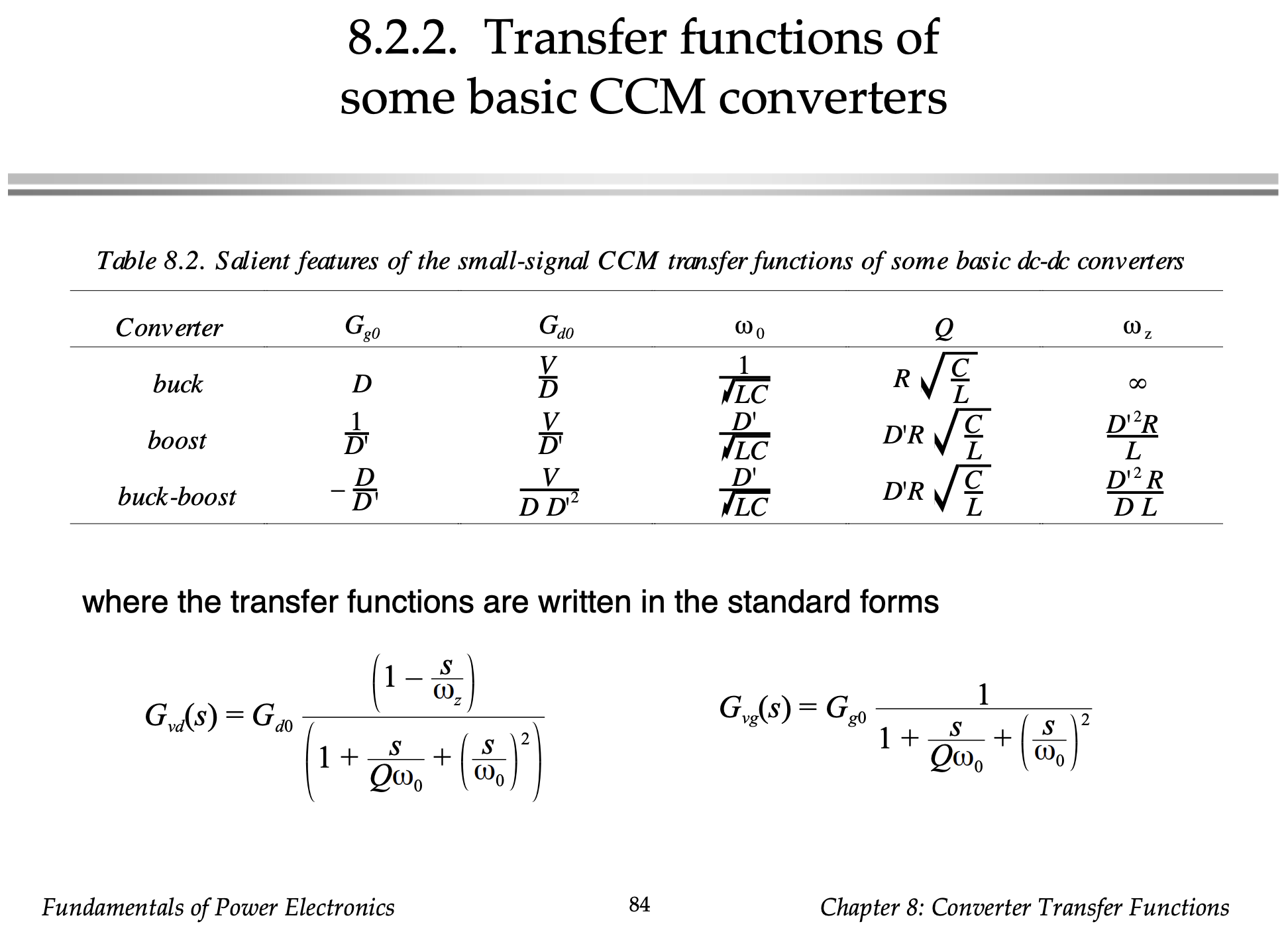
In Ref. [3], the small signal transfer function of Gvd and Gvg for Buck, Boost and Buck-boost are summarized as shown in Fig. 3.

References and downloads
[1] Fundamentals of power electronics - Chapter 2
[2] Popular converters and the conversion ratio derivation
[3] Average Switch Model of Buck Power Stage